
Coherent optical mapping of particles

a particle and optical mapping technology, applied in the field of dynamical imaging systems, can solve the problems of reducing temporal resolution, increasing resolution, and requiring longer measurements,

Active Publication Date: 2013-12-03
THE BOARD OF TRUSTEES OF THE UNIV OF ILLINOIS
View PDF2 Cites 7 Cited by
  • Summary
  • Abstract
  • Description
  • Claims
  • Application Information

AI Technical Summary

Benefits of technology

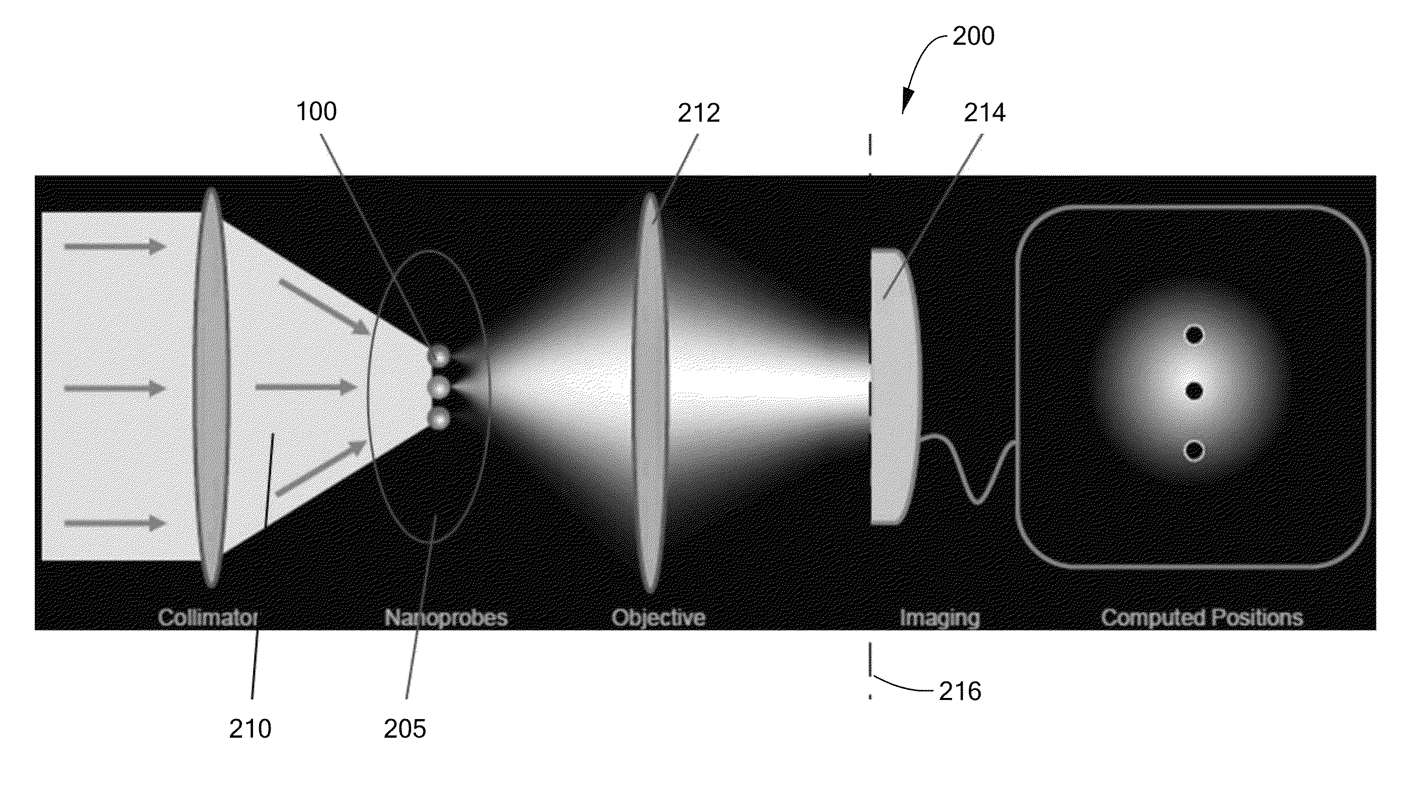
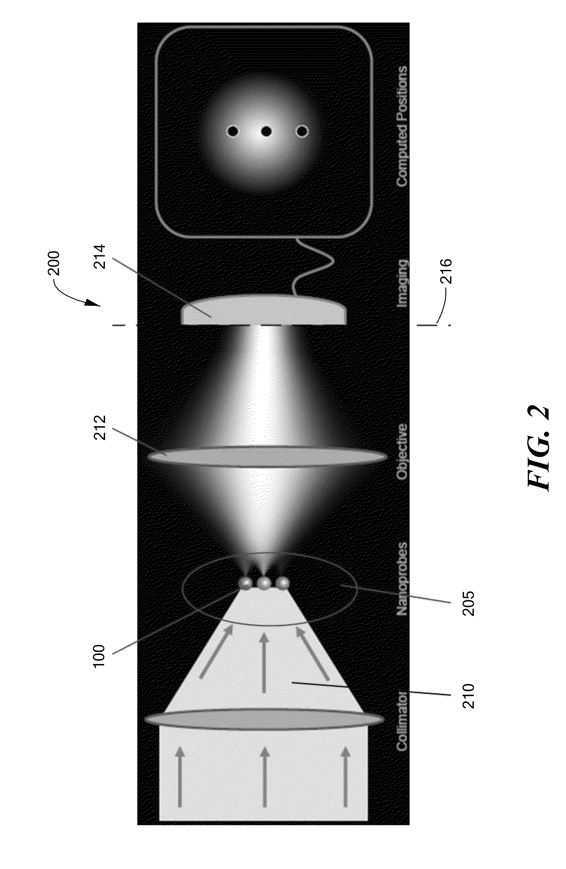
The present invention describes methods and computer program products for simultaneously mapping the positions of multiple nanoprobes with high resolution. The methods involve illuminating the nanoprobes with an electromagnetic wave and detecting the scattered light, before spectrally associating the scattered light with each nanoprobe and mapping its position based on a single measurement. The invention allows for the mapping of a position in three dimensions and can be used with microspheres linked to specific analytes. The computer program product includes a computer-readable medium with computer-readable non-transitory program code for spectrally associating scattered light with nanoprobes and mapping their positions.

Problems solved by technology

While imaging is a problem of estimating the components of a vector in an infinite-dimensional Hilbert space, and is limited by bandwidth, mapping is a series of problems each requiring an estimate of two or three components of a vector in a two- or three-dimensional Hilbert space and limited by signal-to-noise ratio (SNR).
Thus, increased resolution requires longer measurements.
As a consequence of the fact that spatial mapping precision depends on the isolation of emission events in time, the major limiting factor of PALM / STORM methods is the intrinsic trade-off between spatial and temporal resolution, making them slower and less suitable than conventional microscopy for dynamic samples.
While spatial resolution may be improved by measuring for a longer period, this leads to a reduced temporal resolution.
Applications are therefore mainly limited to static or slowly-changing samples.
As a result, resolution in PALM / STORM approaches has reached a practical limit dictated by the intrinsic properties of the process as well as by available technology.

Method used


Image

  • Coherent optical mapping of particles
  • Coherent optical mapping of particles
  • Coherent optical mapping of particles

Examples


Embodiment Construction

[0007]In accordance with preferred embodiments of the present invention, methods and computer program products are provided for simultaneously mapping positions of a plurality of spectrally distinguishable nanoprobes with resolution greater than diffraction-limited resolution. The methods have steps of:[0008]a. illuminating the plurality of nanoprobes with an illuminating electromagnetic wave;[0009]b. detecting light scattered by the plurality of nanoprobes;[0010]c. spectrally associating scattered light with respective nanoprobes; and[0011]d. mapping, based on a single measurement, a position associated with each nanoprobe.

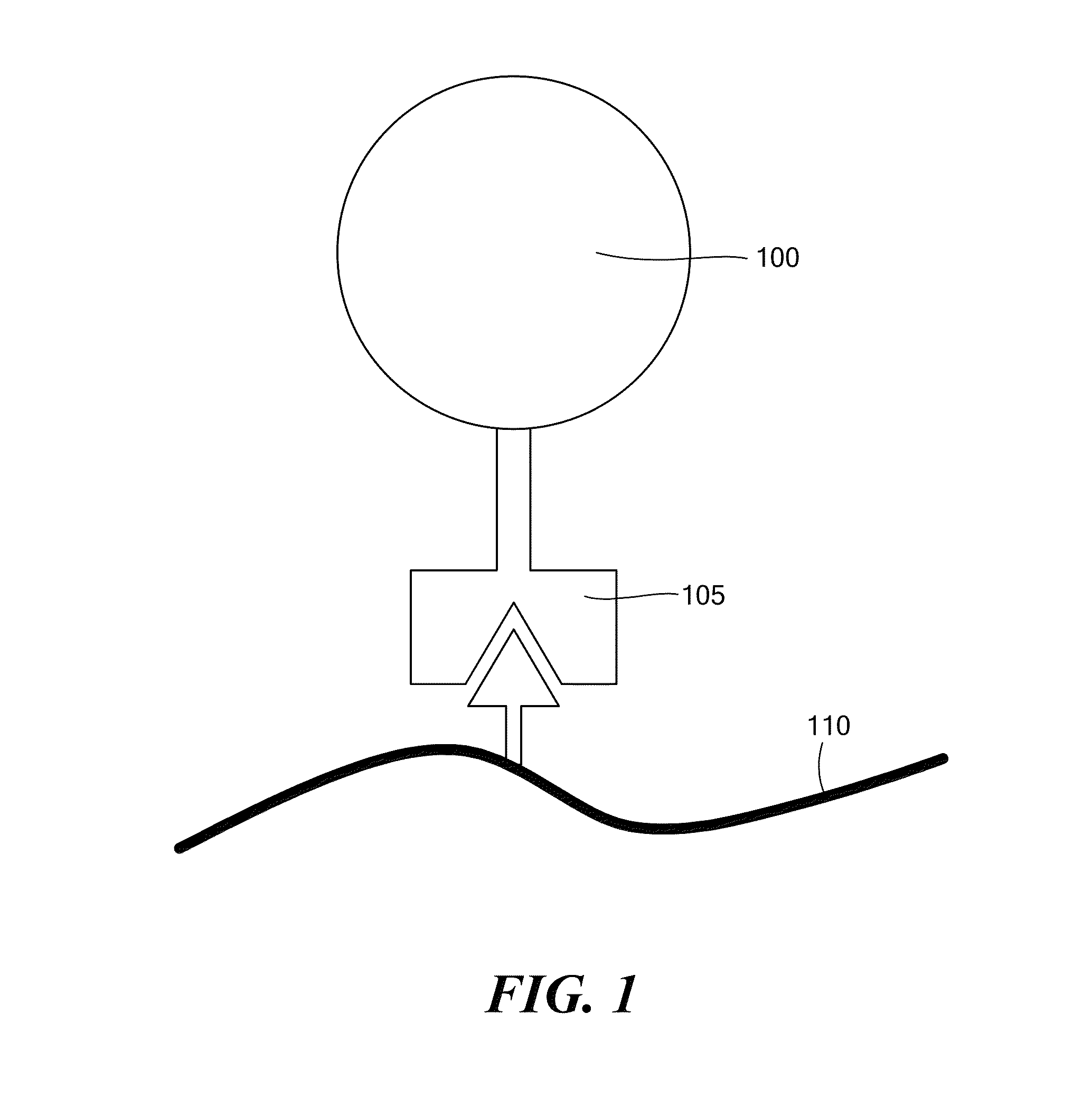
[0012]In accordance with further embodiments of the invention, the spectrally distinguishable nanoprobes may be linked to at least one specified analyte. The spectrally distinguishable nanoprobes may be microspheres. The step of spectrally associating may include projection of the total signal onto a spectral response of each nanoprobe at each of a plurality of p...


PUM


Abstract

Methods and computer program products for super-resolution mapping of nanoprobes having spectrally distinguishable coherent scattering properties. A sample containing a plurality of nanoprobes is illuminated with broadband light, and coherent scattering by the nanoprobes is detected. Scattered light is spectrally associated with respective nanoprobes, allowing a position associated with each nanoprobe to be mapped.

Description

[0001]Portions of this invention were developed with Government support under grant CHE0957849, awarded by the National Science Foundation. The Government has certain rights in the invention.TECHNICAL FIELD OF THE INVENTION[0002]The present invention pertains to imaging dynamical systems at nanometer resolution by means of nanoprobes with distinguishable spectral responses, and, more particularly, to mapping of nanoprobes on the basis of coherent scattering.BACKGROUND OF THE INVENTION[0003]Subcellular structures are unresolvable by classical optical techniques as such structures are smaller than the resolution limit, as described by Abbe, Beiträge zur Theorie des Mikroskops and der mikroskopischen Wahrnehmung, Arch. Mikroskop. Anat. 9, 413-18 (1873). Super-resolved fluorescence microscopy techniques have been developed to overcome this long-standing far-field resolution barrier in recent years, as described by Hell, et al., Far-field optical nanoscopy, Science 316, 1153-58 (2007), a...

Claims


Application Information

Patent Timeline
IPC IPC(8): G01B11/14
CPCG01N21/6428G01N21/6458B82Y15/00A61B5/0059A61B5/065
Inventor VAN DIJK, THPOMASMAYERICH, DAVIDBHARGAVA, ROHITCARNEY, PAUL SCOTT
Owner THE BOARD OF TRUSTEES OF THE UNIV OF ILLINOIS
Learn More