
Input current shaping for transition and discontinuous mode power converter

a power converter and discontinuous mode technology, applied in the direction of generating/distributing signals, pulse techniques, instruments, etc., can solve the problems of converters not being able to maintain the transition mode switching conditions, deteriorating performance, and starting to work

Active Publication Date: 2013-12-03
BEL POWER SOLUTIONS INC
View PDF6 Cites 3 Cited by
  • Summary
  • Abstract
  • Description
  • Claims
  • Application Information

AI Technical Summary

Problems solved by technology

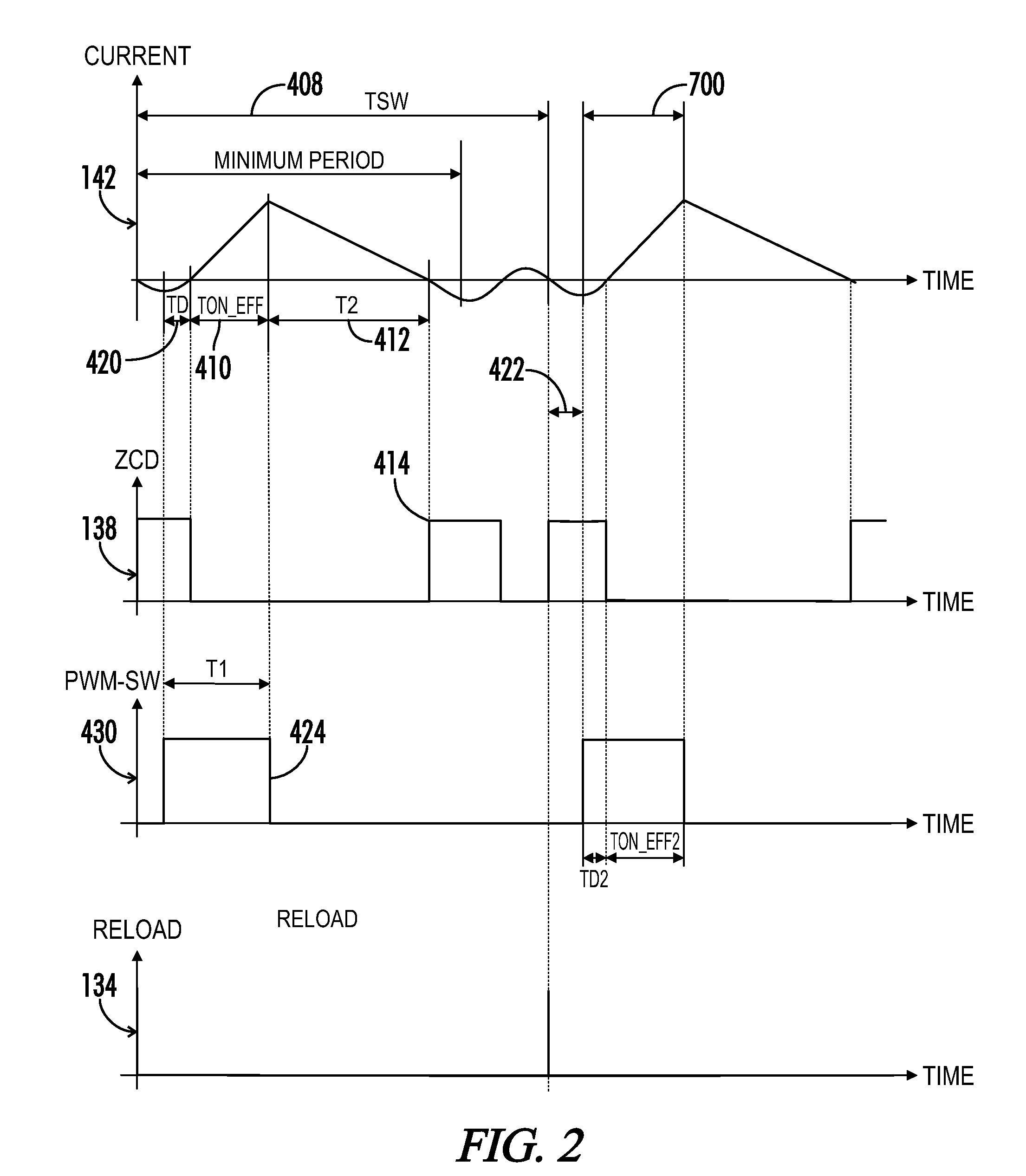
While in theory the current of a power converter operating in the transition mode with a constant on-time switching scheme is always proportional to and in phase with the input voltage, practical limitations deteriorate the performance which results in a total-harmonic-distortion (THD) value that is unacceptable in certain applications.
As a result, the converter is not able to maintain the transition mode switching conditions and starts to work in the discontinuous switching mode where the average input current using a constant on-time switching scheme is not proportional to the input voltage.
This improves the THD at the cost of reduced efficiency due to increased driving and switching losses.
However, the THD of the input current is still negatively affected close to the polarity changes of the input voltage.
As a result of the small input voltage, the stored energy in the inductor becomes very small and is not able to commutate the boost diode due to the parasitic capacitances of the switching node.
A shortcoming of this method is that the average input current over one switching cycle needs to be sensed, which increases the cost and complexity for the control and current sensing.

Method used


Image

  • Input current shaping for transition and discontinuous mode power converter
  • Input current shaping for transition and discontinuous mode power converter
  • Input current shaping for transition and discontinuous mode power converter

Examples


Embodiment Construction

[0021]While the making and using of various embodiments of the present invention are discussed in detail below, it should be appreciated that the present invention provides many applicable inventive concepts that can be embodied in a wide variety of specific contexts. The specific embodiments discussed herein are merely illustrative of specific ways to make and use the invention and do not delimit the scope of the invention.

[0022]To facilitate the understanding of the embodiments described herein, a number of terms are defined below. The terms defined herein have meanings as commonly understood by a person of ordinary skill in the areas relevant to the present invention. Terms such as “a,”“an,” and “the” are not intended to refer to only a singular entity, but rather include the general class of which a specific example may be used for illustration. The terminology herein is used to describe specific embodiments of the invention, but their usage does not delimit the invention, excep...


PUM


Abstract

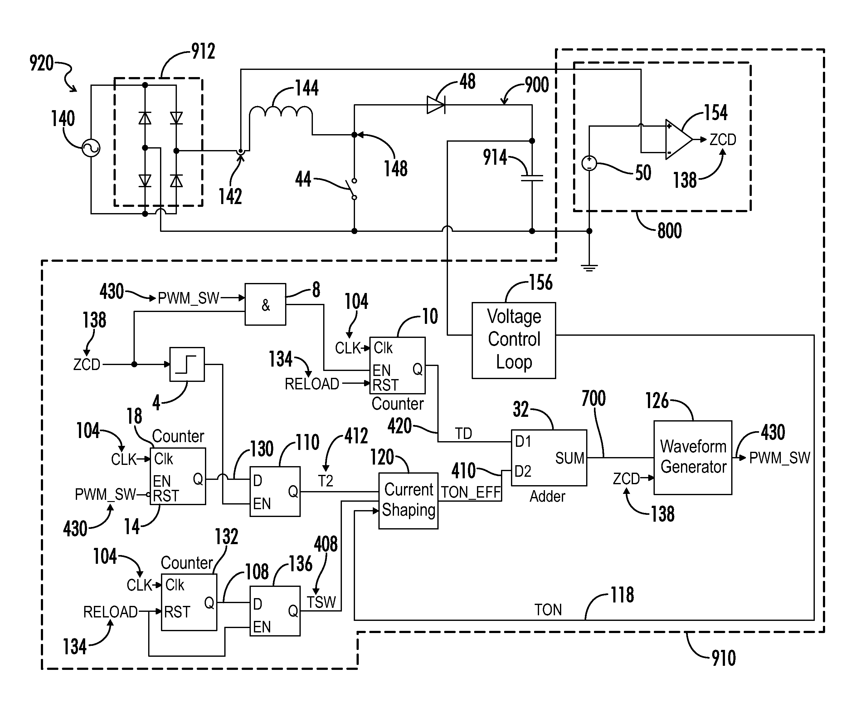
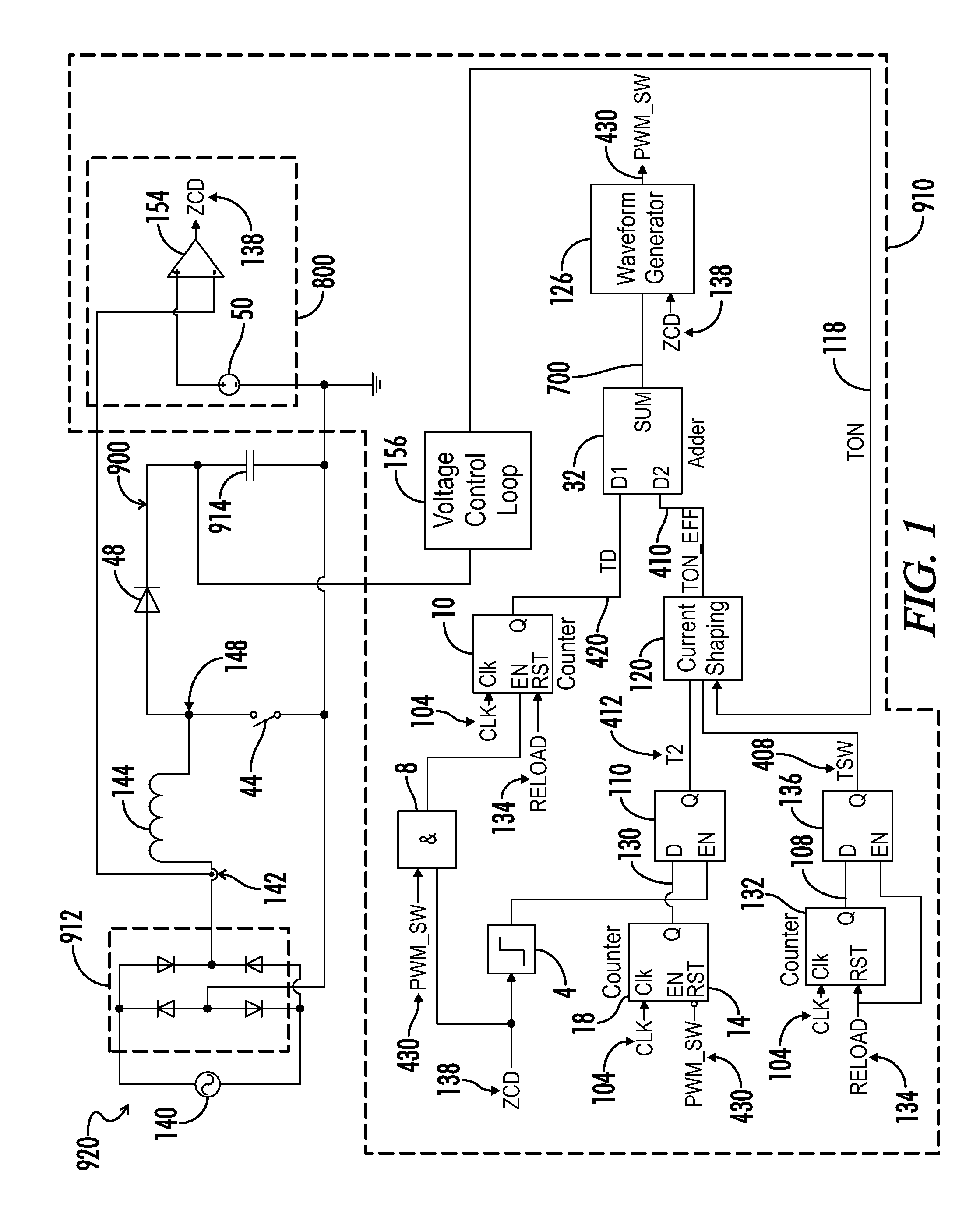
A power converter operable to draw an input current that is in phase with an input voltage of the power converter and proportional to a voltage of the input voltage of the power converter includes a drive switch, a waveform generator, and a current shaping circuit. The drive switch is connected between an input inductor and ground and draws current through the input inductor when turned on. The current shaping circuit provides an on-time of the drive switch for a next cycle of the drive switch as a function of an input current decay time, a switching period of the waveform generator, and an output voltage of the power converter. The waveform generator is responsive to the on-time provided by the current shaping circuit for selectively turning the drive switch on and off to cycle the drive switch as a function of the received on-time.

Description

CROSS-REFERENCES TO RELATED APPLICATIONS[0001]This application claims benefit of the following patent application which is hereby incorporated by reference: U.S. Provisional Patent Application No. 61 / 441,486, entitled “Input Current Shaping Method for Transition and Discontinues Mode Power Converter”, filed Feb. 10, 2011.[0002]A portion of the disclosure of this patent document contains material that is subject to copyright protection. The copyright owner has no objection to the reproduction of the patent document or the patent disclosure, as it appears in the U.S. Patent and Trademark Office patent file or records, but otherwise reserves all copyright rights whatsoever.STATEMENT REGARDING FEDERALLY SPONSORED RESEARCH OR DEVELOPMENT[0003]Not ApplicableREFERENCE TO SEQUENCE LISTING OR COMPUTER PROGRAM LISTING APPENDIX[0004]Not ApplicableBACKGROUND OF THE INVENTION[0005]This invention relates generally to power factor corrected power converters that work in the transition or discontin...

Claims


Application Information

Patent Timeline
Patent Type & Authority Patents(United States)
IPC IPC(8): H03K3/00
CPCH02M1/4225H02M3/156Y02B70/126Y02B70/10H02M1/42H02M1/12H02M3/158G05F1/70
Inventor ZIEGLER, SILVIOFENO, IVAN
Owner BEL POWER SOLUTIONS INC
Learn More