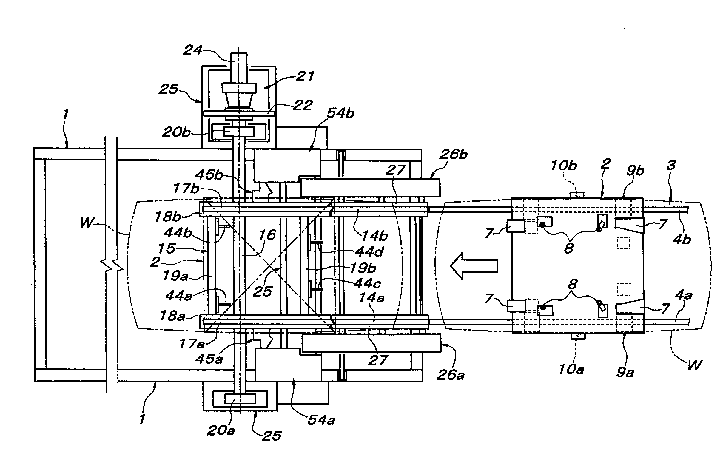
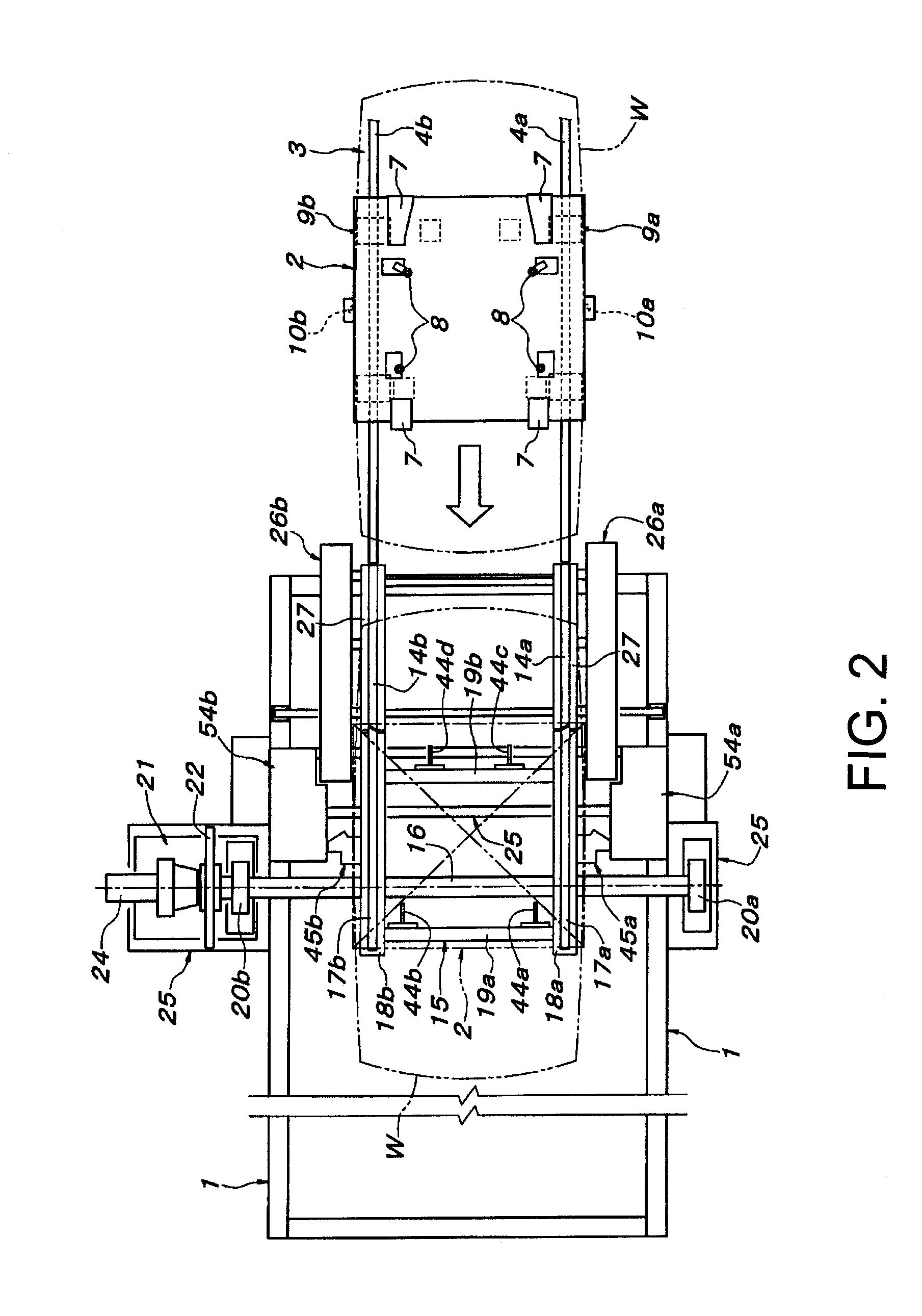
[0011]According to the configuration as set forth in the first aspect of the present invention, the ground traveling path which is connected to the rear end of the rotation base in the waiting posture serves as both an approach path and a retreat path of the conveying traveling body with respect to the rotation base, and the workpiece loaded conveying traveling body whose dipping in the treatment bath is completed by rotation of the rotation base retracts from on the rotation base in the waiting posture and returns to the initial ground traveling path. Since the ground traveling path to make the conveying traveling body leave is not provided at the front end of the rotation base, there is no need to adopt such a complex configuration that guide rails or roller conveyors constituting the retract ground traveling path are allowed to escape to lateral both sides as in the conventional manner even if the rotation base is configured to pivotally be supported by the horizontal spindle at a position where the rear end thereof projects forward largely when rotated forwardly downward from the waiting posture, that is, at a position near the front end thereof. Consequently, the configuration of the entire apparatus can be rendered simple and be carried out inexpensively.
[0012]Further, a fixed stopper structure to receive the conveying traveling body having moved onto the rotation base in the waiting posture at a fixed position can be incorporated into the positioning and fixing device which is necessary for the rotation base. Therefore, the configuration of the positioning and fixing device becomes simple and can be carried out inexpensively in this respect, too.
[0013]On the other hand, according to the configuration as set forth in the second aspect, the front-back direction length of the treatment bath can be shortened as compared with the case where the rotation base is pivotally supported by the horizontal spindle at the central position in the back and forth direction of the rotation base (the central position in the back and forth direction of the workpiece such as vehicle body on the conveying traveling body having been positioned and fixed on the rotation base), as described above. At the same time, the rotation base can be supported in the waiting posture reliably and stable only by the support mechanism to receive the rear end of the rotation base. In that case, the configuration as set forth in the third aspect can make the receiver of the support mechanism efficiently receive loads of the workpiece loaded conveying traveling body which act upon the rotation base and also can prevent lateral swinging of the rotation base reliably, such that the conveying traveling body can be moved onto and leave the rotation base safely.
[0014]According to the configuration as set forth in the fourth aspect, the engaged pins provided at at least two places at the front and rear of the rotation base and the fixed positioning members corresponding to those engaged pins and provided at the rotation base can reliably exert both functions of stopping the conveying traveling body having moved onto the rotation base at a fixed position and of preventing dropping of the conveying traveling body when the rotation base is flipped upside down. Then, the positioning and fixing device to position and fix the conveying traveling body at a fixed position on the rotation base can be configured by a remarkably simple structure of adding as safety measures the locking movable piece which prevents the conveying traveling body from retracting. In that case, the retracting movement of the conveying traveling body on the rotation base can reliably be prevented by the locking movable piece according to the configuration as set forth in the fifth aspect. As long as the shape and pivotal support position of the locking movable piece is preconsidered such that the locking movable piece does not move toward the fixation released direction by an acting force acting thereon from the locked member of the conveying traveling body when a retracting force acts upon the conveying traveling body on the rotation base, safety can be enhanced by a simple structure of only adding a spring capable of holding the locking movable piece in the fixation active state and in the fixation released state.
[0015]Furthermore, according to the configuration as set forth in the sixth aspect, the locking movable piece held in the fixation active state or the fixation released state by the spring force as described above can be switched to the opposite state reliably by the two operating pieces and the driving actuators therefore. Further, according to the configuration as set forth in the seventh aspect, an actuator such as a cylinder unit as mechanism to switch the locking movable piece between the locking active state and the locking released state is unnecessary, and the positionally fixed operation member and the spring can switch the locking movable piece between the locking active state and the locking released state. Thus, the apparatus of the present invention can be carried out easily and inexpensively.