
Magnetic resonance imaging apparatus and multi-contrast acquiring method

a magnetic resonance imaging and multi-contrast acquisition technology, applied in the field of multi-echo sequence techniques, can solve the problems of increasing the total imaging time, inadequate signal-to-noise ratio, and deteriorating contrast of images obtained by reconstructing such k-space data, so as to reduce imaging time, improve contrast of respective images, and improve image contrast

Active Publication Date: 2013-11-19
FUJIFILM HEALTHCARE CORP
View PDF7 Cites 3 Cited by
  • Summary
  • Abstract
  • Description
  • Claims
  • Application Information

AI Technical Summary

Benefits of technology

[0028]In accordance with the above-described configuration, in the imaging using a multi-echo sequence based on the radial sampling method, the present invention is capable of simultaneously obtaining a plurality of images having different contrasts in one time of imaging without prolonging imaging time. Furthermore, contrast of the respective images is improved compared to the images obtained by reconstructing the measured echo signal groups without dividing the measured echo signal groups.
[0030]In this manner, it is possible to obtain an image having two or more different contrasts while maintaining the number of echo signals to be acquired minimum.
[0036]By doing so, contrast of the image can be further improved.
[0037]The MRI apparatus of the present invention is capable of reconstructing a plurality of images having different contrasts by dividing the echo signal group measured by a multi-echo sequence based on the radial sampling method into a plurality of sections and respectively reconstructing images from the divided partial echo signal groups. Also, contrast of the respective images is improved compared to the images obtained by reconstructing the measured echo signal groups without dividing. Furthermore, since a plurality of images having different contrasts can be obtained in one time of imaging, the imaging time can be reduced compared to the method which repeats imaging for a plurality of times.

Problems solved by technology

The image obtained by reconstructing such K-space data tends to have deteriorated contrast.
However, the former method has a demerit that the total imaging time has to be increased due to increase of the number of applications of a high-frequency magnetic field, and the latter method also has a demerit of inadequate signal-to-noise ratio due to increase of the reception bandwidth or lowering of the spatial resolution due to decrease in the number of acquired matrix.

Method used


Image

  • Magnetic resonance imaging apparatus and multi-contrast acquiring method
  • Magnetic resonance imaging apparatus and multi-contrast acquiring method
  • Magnetic resonance imaging apparatus and multi-contrast acquiring method

Examples


first embodiment

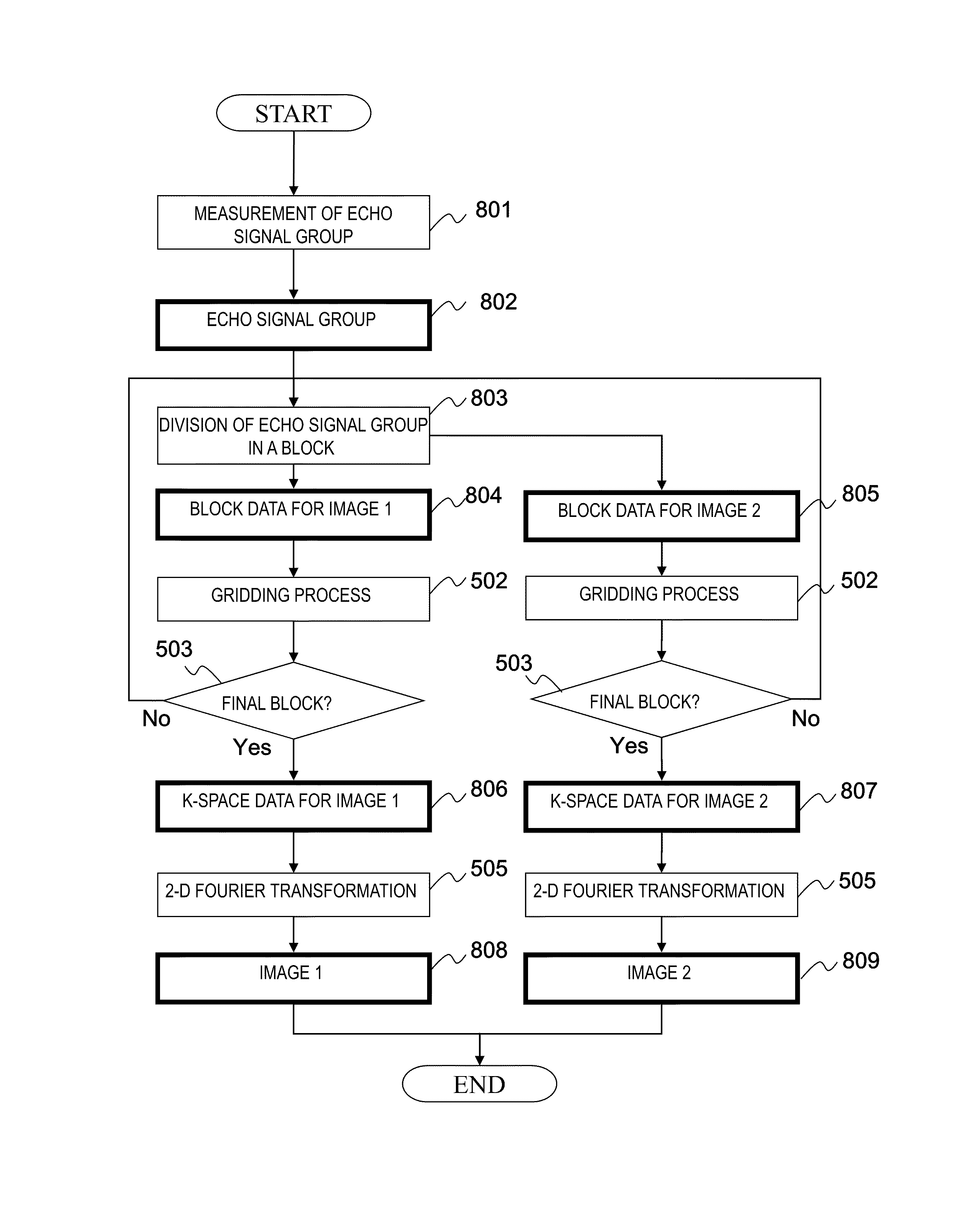
[0085]Next, the first embodiment of the MRI apparatus and multi-contrast image acquisition method related to the present invention will be described. The present embodiment divides the respective echo signals of one or more blocks measured by the sequence of the hybrid radial method into a plurality of partial echo signal groups, and reconstructs an image respectively having different contrasts using each of the divided partial echo signal groups. Further, upon dividing the echo signal group of one or more blocks, one or more echo signals from among the echo signal group are to be overlapped with two or more of the plurality of partial echo signal groups. The present embodiment will be described below in detail using the attached diagrams.

[0086]First, the outline of the present embodiment will be described referring to FIGS. 6 and 7.

[0087]FIG. 6(a) shows echo signal group 601 in one time of repetition 211 measured by executing the sequence of the hybrid radial method shown in FIG. 4...

second embodiment

[0110]Next, the second embodiment of the MRI apparatus and multi-contrast image acquisition method related to the present invention will be described. While an example that the echo signal group of the block is divided so that the numbers of echo signals to be collected as each partial echo signal group are to be approximately the same as described in the first embodiment, the present embodiment divides the echo signal group of the block, with respect to the echo signal group of one or more blocks, by differentiating the numbers of echo signals to be collected as a partial echo signal group. All but this point is the same as the first embodiment. Only the difference from the first embodiment will be described below based on FIG. 9, and the explanation on the same part will be omitted.

[0111]FIG. 9(a) shows echo signal group 901 in one time of repetition 211 measured by executing the sequence by the hybrid radial method shown in FIG. 4, illustrating the case that 14 echo signals are m...

third embodiment

[0123]Next, the third embodiment of the MRI apparatus and multi-contrast image acquisition method related to the present invention will be described. While an example is described in the first embodiment that an echo signal group in a block is divided by overlapping the same echo signal with a plurality of partial echo signal groups, the present embodiment divides an echo signal group in a block without overlapping the same echo signal with a plurality of partial echo signal groups, i.e. by differentiating the echo signal for every partial echo signal groups. All but this point is the same as the first embodiment. Only differences of the present embodiment from the first embodiment will be described below referring to FIG. 11, and explanation on the same content will be omitted.

[0124]In order not to overlap the same echo signal with a plurality of partial echo signal groups, the present embodiment measures a part of echo signals corresponding to the low-spatial frequency region in t...


PUM


Abstract

The contrast of an image obtained by using a multi-echo sequence with hybrid-radial sampling is improved by dividing echo signal groups of one or more blocks measured by executing the imaging using the multi-echo sequence, into a plurality of partial echo signal groups, each of which is used to reconstruct an image with different contrast from each other.

Description

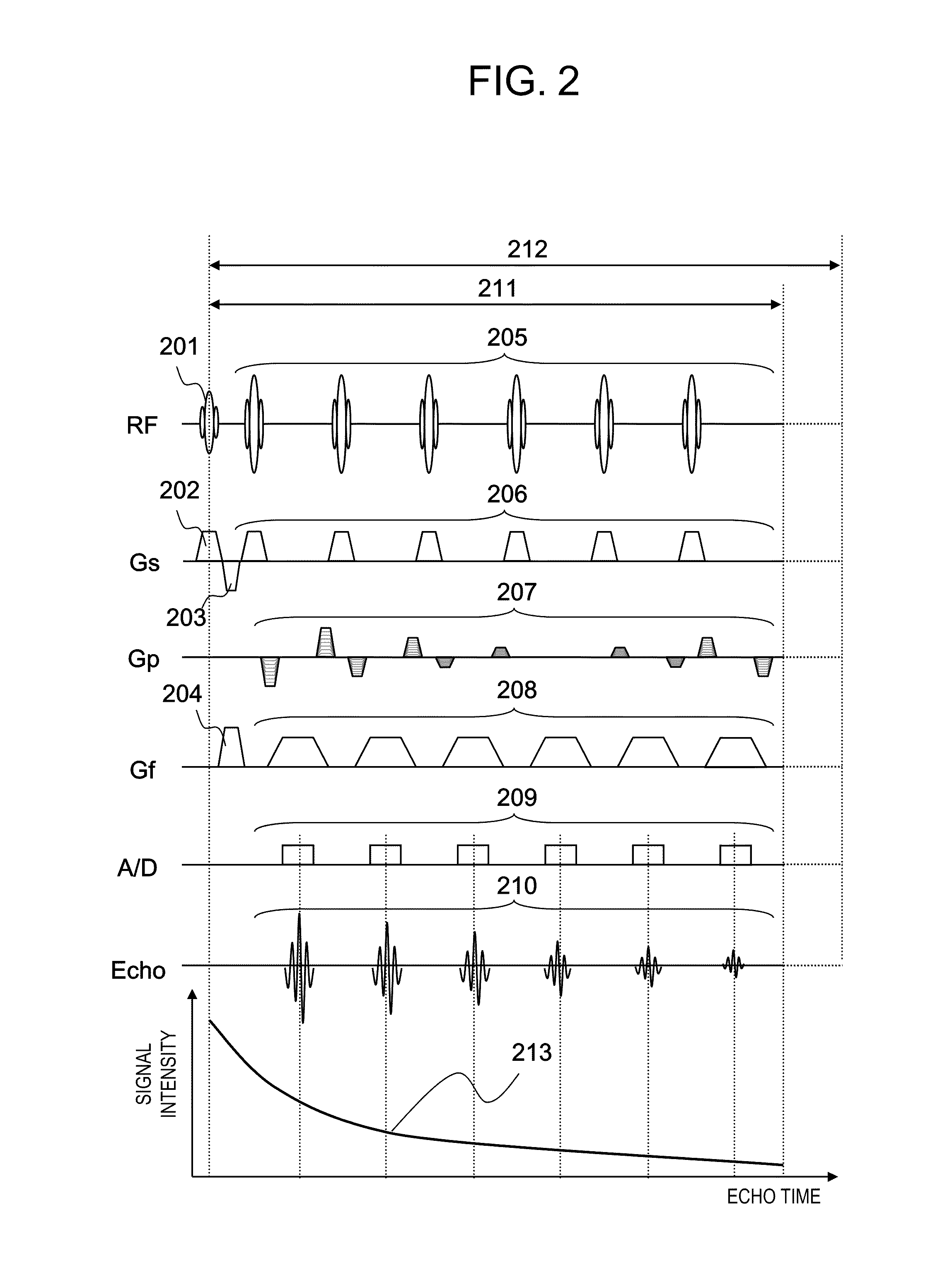
FIELD OF THE INVENTION[0001]The present invention is related to a technique of multi-echo sequence using the radial sampling method in a magnetic resonance imaging (hereinafter referred to as MRI) apparatus that obtains a tomographic image of an examination region in an object to be examined using nuclear magnetic resonance (hereinafter referred to as NMR) phenomenon.DESCRIPTION OF THE RELATED ART[0002]In MRI apparatuses, when an object moves during imaging, artifacts which appear as if the image streaked in the phase encode direction (hereinafter referred to as body-movement artifacts) are generated which affect the entire image. This phenomenon is caused, upon sampling the echo signal of the respective lattice points on a measurement space (so-called “K-space”, and hereinafter referred to as K-space), generally because the sampling which is parallel to the frequency encode direction is repeated in the phase encode direction (hereinafter referred to as “Cartesian sampling method”)....

Claims


Application Information

Patent Timeline
Patent Type & Authority Patents(United States)
IPC IPC(8): G01V3/00
CPCG01R33/4824G01R33/561G01R33/5617G01R33/5608G01R33/5615G01R33/56509G01R33/5676
Inventor TAKIZAWA, MASAHIRO
Owner FUJIFILM HEALTHCARE CORP
Learn More