
Mattress foundation corner connector and bed frame assembly

a mattress foundation and corner connector technology, applied in the direction of beds, beds, fastening means, etc., can solve the problems of requiring many components and tools, requiring relatively skilled workers, and constructing mattress foundations using known methods, and achieves the effect of less expensive manufacturing and improved design

Inactive Publication Date: 2013-11-19
ROBERTS THOMAS A
View PDF30 Cites 31 Cited by
  • Summary
  • Abstract
  • Description
  • Claims
  • Application Information

AI Technical Summary

Benefits of technology

The patent is about a mattress foundation assembly that is made up of medium-density fiberboard and / or plastic components. This design has a much lower part count compared to other foundations, reducing the likelihood of squeaks and other friction-related issues. The patent also introduces a lightweight corner connector element.

Problems solved by technology

However, constructing mattress foundations using known methods is typically time-consuming, requires relatively skilled workers, requires numerous components and tools, and does not always result in a secure or square mattress foundation.

Method used


Image

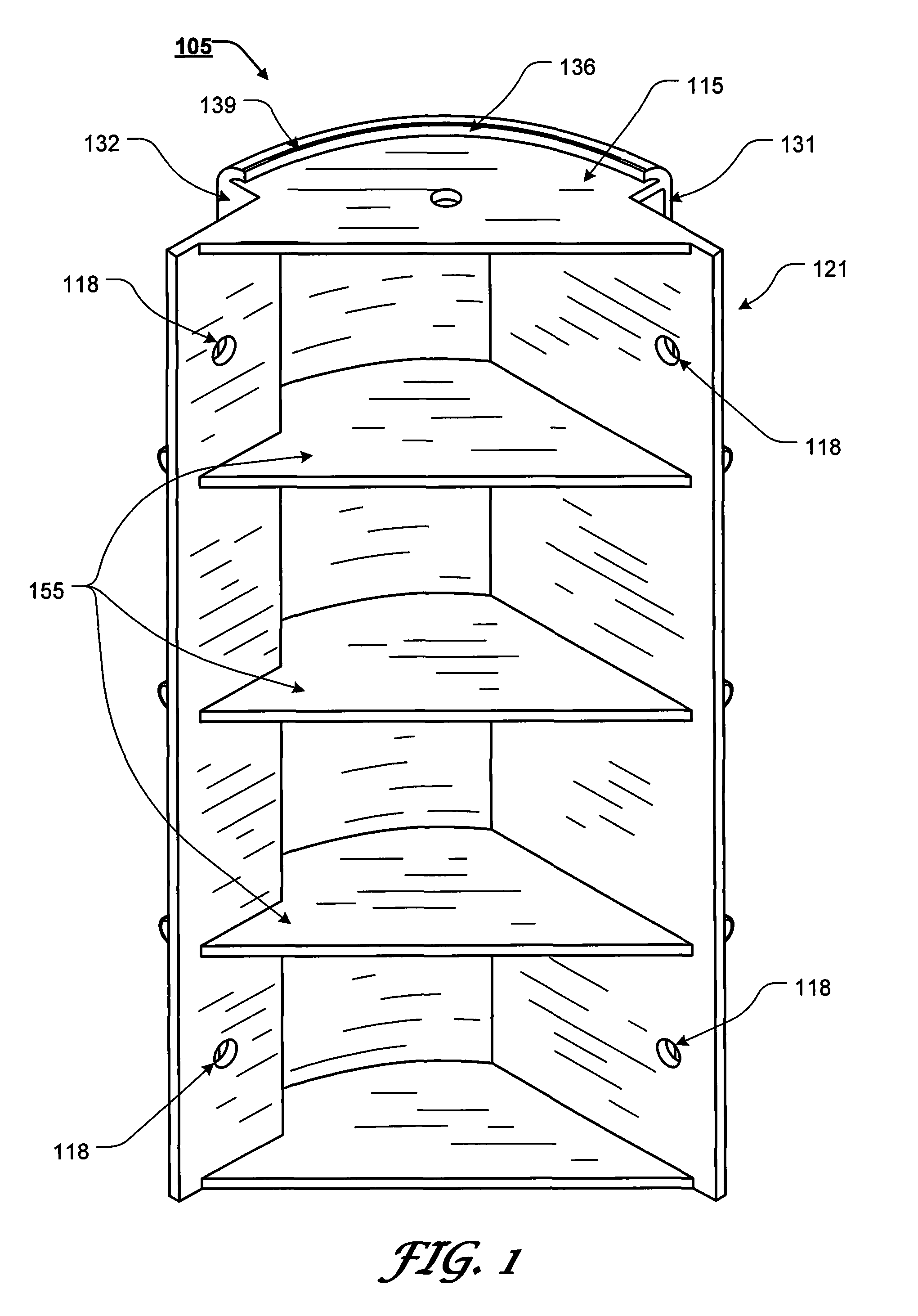
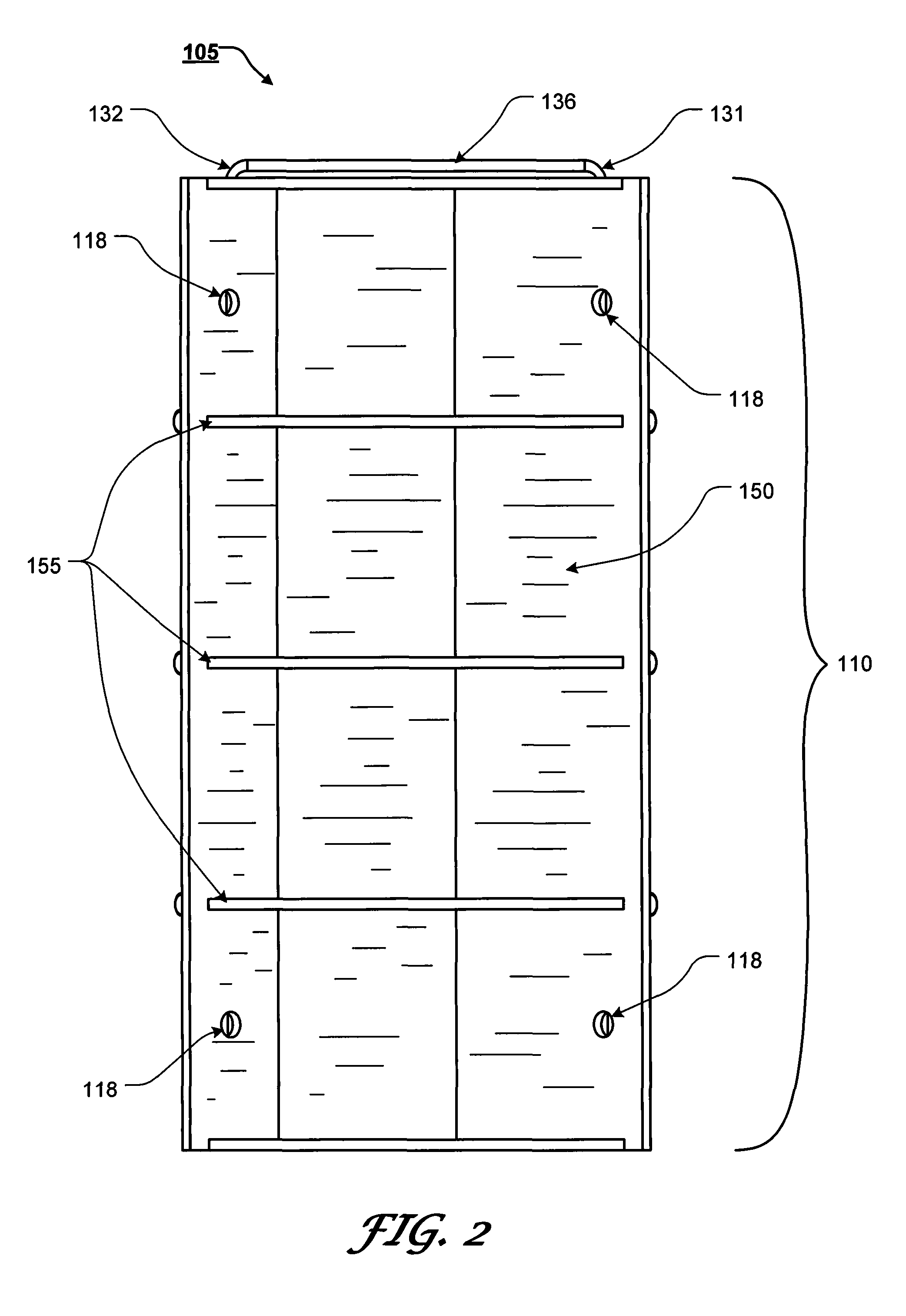
  • Mattress foundation corner connector and bed frame assembly
  • Mattress foundation corner connector and bed frame assembly
  • Mattress foundation corner connector and bed frame assembly

Examples


Embodiment Construction

[0090]For simplicity and clarification, the design factors and operating principles of the mattress foundation corner connectors and mattress foundation assemblies according to this invention are explained with reference to various exemplary embodiments of mattress foundation corner connectors and / or mattress foundation assemblies according to this invention. The basic explanation of the design factors and operating principles of the mattress foundation corner connectors and mattress foundation assemblies is applicable for the understanding, design, and operation of the mattress foundation corner connectors and mattress foundation assemblies of this invention. It should be appreciated that the mattress foundation corner connectors and / or the mattress foundation assemblies can be adapted to many applications where a simplified corner connector and / or a foundation assembly is needed.

[0091]It should also be appreciated that the terms “mattress foundation”, “mattress foundation assembly...


PUM


Abstract

A corner connector having a pie-shaped body portion formed by a first abutment surface, a second abutment surface, and a radiused surface, wherein the first abutment surface and the second abutment surface are formed at substantially 90° relative to one another; wherein a first portion of the first abutment surface extends from a substantially planar bottom surface to a substantially planar deck panel support surface and wherein a second portion of the first abutment surface extends from the bottom surface above the deck panel support surface; wherein a first portion of the second abutment surface extends from the bottom surface to the deck panel support surface and wherein a second portion of the second abutment surface extends from the bottom surface above the deck panel support surface; and one or more protrusions extend perpendicularly from the first abutment surface and the second abutment surface.

Description

CROSS-REFERENCE TO RELATED APPLICATIONS[0001]This is a Continuation-In-Part of co-pending U.S. patent application Ser. No. 12 / 931,329, filed Jan. 28, 2011, which is a Continuation-In-Part of U.S. patent application Ser. No. 12 / 661,068, filed Mar. 10, 2010 (U.S. Pat. No. 7,900,300), which is a Continuation-In-Part of U.S. patent application Ser. No. 12 / 152,194, filed May 13, 2008 (U.S. Pat. No. 7,703,155), the disclosures of which are incorporated herein by reference in their entireties.STATEMENT REGARDING FEDERALLY SPONSORED RESEARCH OR DEVELOPMENT[0002]Not applicable.NOTICE OF COPYRIGHTED MATERIAL[0003]The disclosure of this patent document contains material that is subject to copyright protection. The copyright owner has no objection to the reproduction by anyone of the patent document or the patent disclosure, as it appears in the Patent and Trademark Office patent file or records, but otherwise reserves all copyright rights whatsoever. All trademarks and service marks identified...

Claims


Application Information

Patent Timeline
Patent Type & Authority Patents(United States)
IPC IPC(8): A47C19/00
CPCA47C19/005A47C19/021F16B12/46F16B12/54
Inventor ROBERTS, THOMAS A.
Owner ROBERTS THOMAS A
Learn More