Electric linear motion actuator and electric brake system

a technology of linear motion and actuator, which is applied in the direction of gearing, transportation and packaging, hoisting equipment, etc., can solve the problems of increasing the size of the entire electric linear motion actuator, hampering the smooth linear motion of the carrier or the linear motion member, and the conversion mechanism alone cannot sufficiently increase the driving force, etc., to achieve smooth linear motion, smooth linear motion of the output member, and stable transmission of the torque of the rotary shaft

Active Publication Date: 2013-11-12
NTN CORP
View PDF35 Cites 16 Cited by
  • Summary
  • Abstract
  • Description
  • Claims
  • Application Information

AI Technical Summary

Benefits of technology

[0008]An object of the present invention is to allow smooth guidance of the linear motion of the output member even when a lateral moment acts on the output member, and to make it possible to stably transmit torque of the rotary shaft to the respective planetary rollers without applying a preload to the planetary rollers by negative gaps between the rollers and the radially outer surface of the rotary shaft and between the rollers and the radially inner surface of the outer race member.

Problems solved by technology

But this motion converting mechanism alone cannot sufficiently increase the driving force as required by e.g. an electric brake system.
But the addition of such a separate speed reducer increases the size of the entire electric linear motion actuator.
This lateral moment may hamper smooth linear motion of the carrier or the linear motion member.
This makes smooth linear motion of the linear motion member even more difficult.
It is thus troublesome and time-consuming to finish the rotary shaft and outer race member and then mount the planetary rollers.
This increases the manufacturing cost.

Method used


Image

  • Electric linear motion actuator and electric brake system
  • Electric linear motion actuator and electric brake system
  • Electric linear motion actuator and electric brake system

Examples


Embodiment Construction

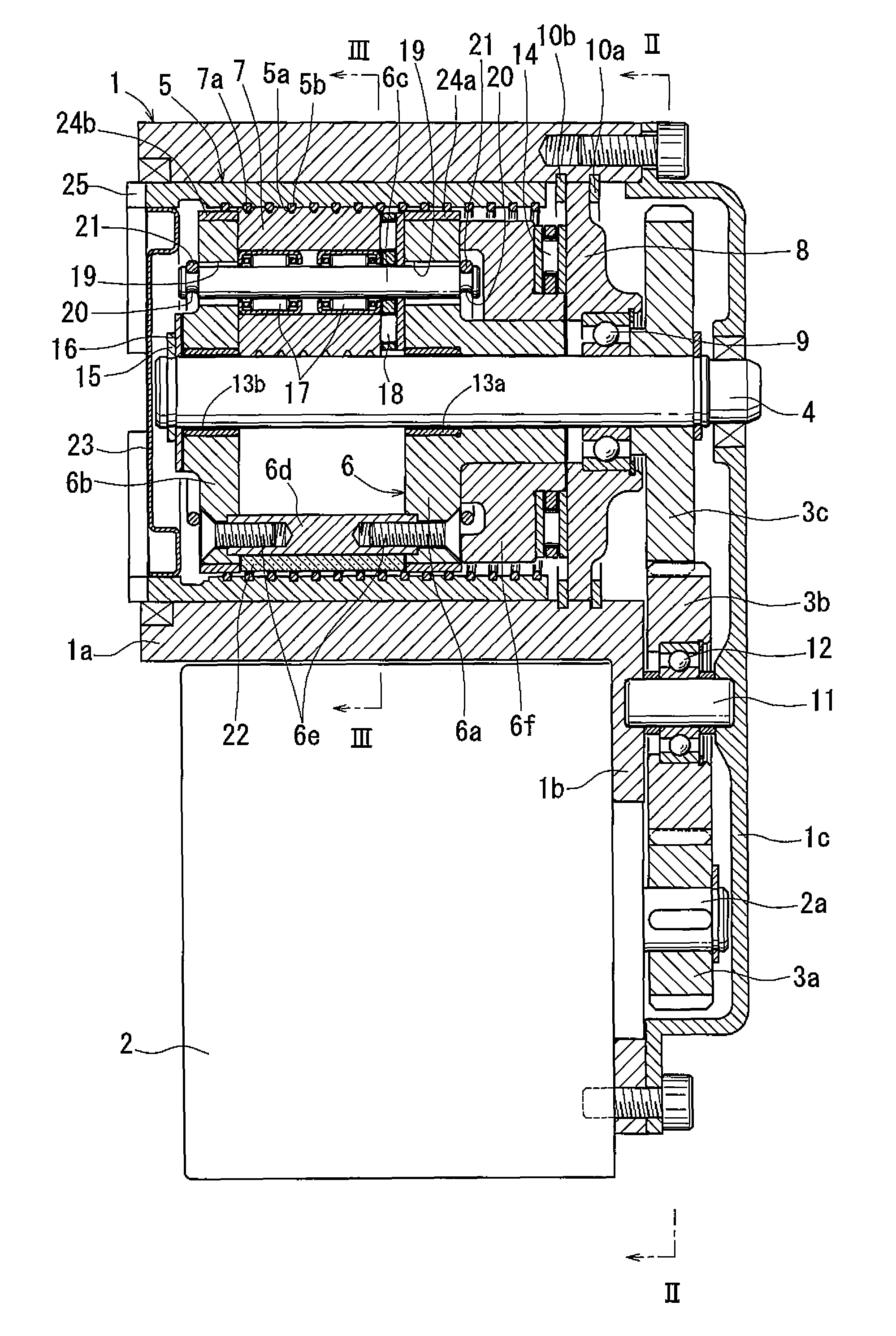
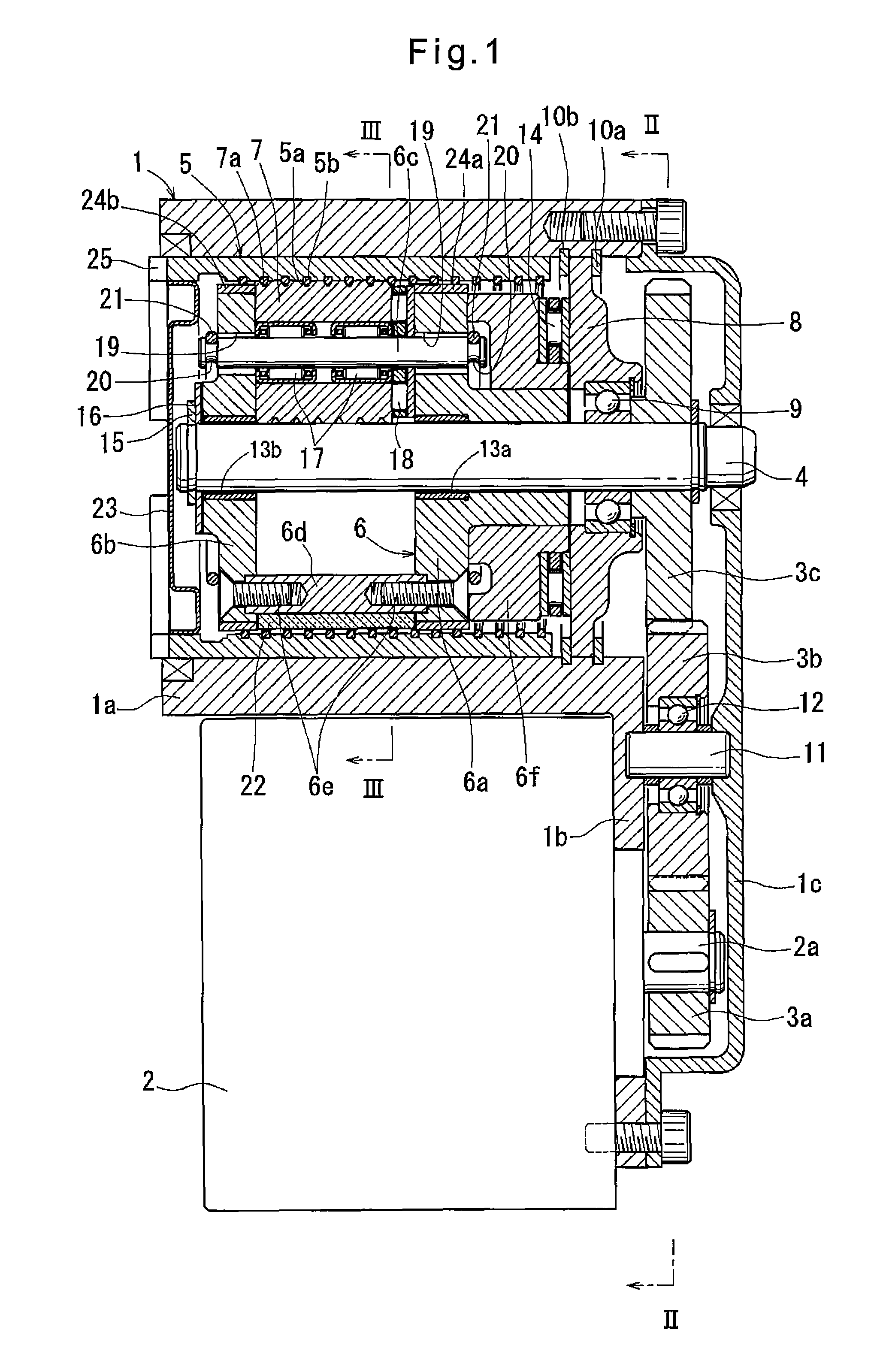
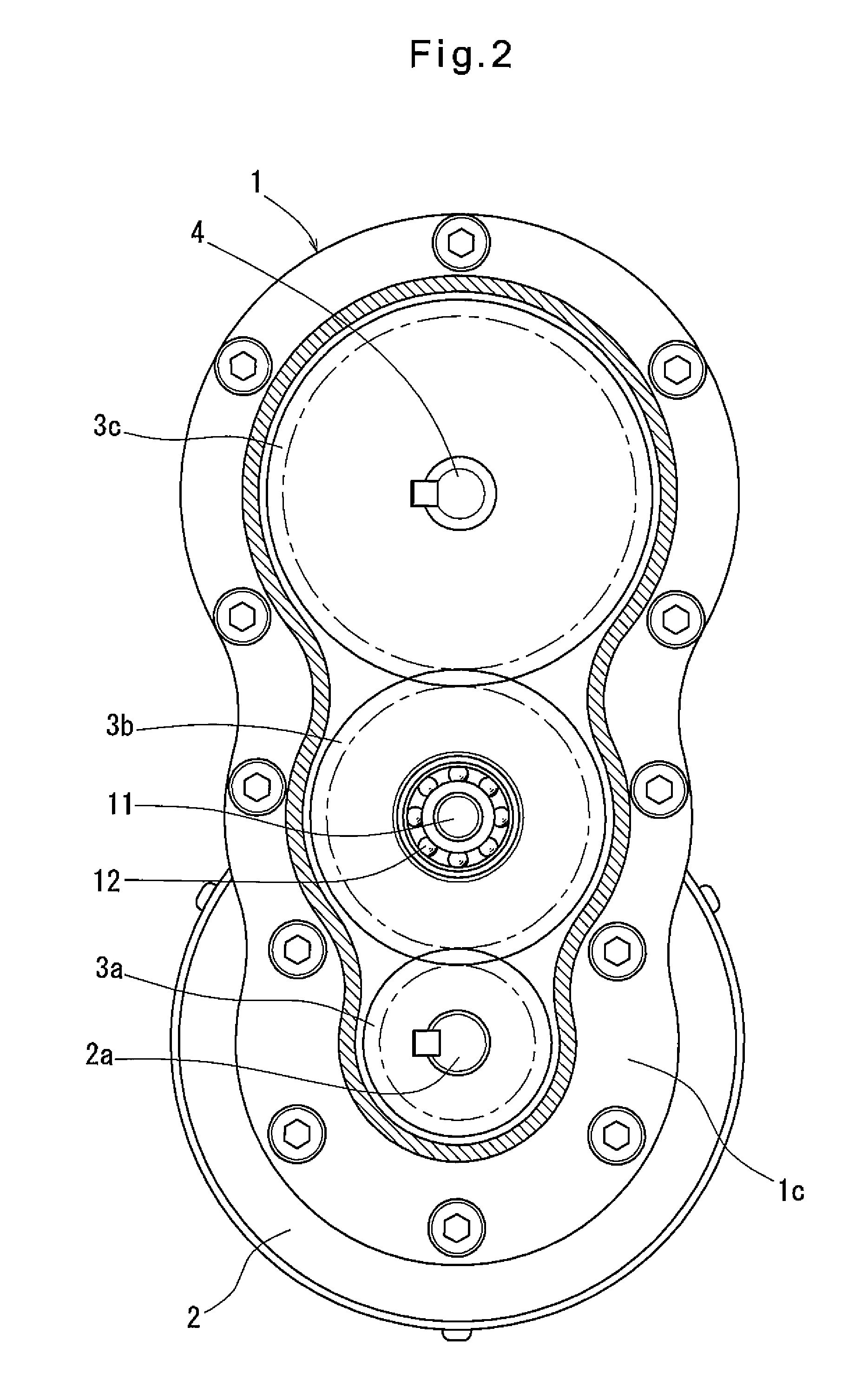
[0027]Now the embodiment of the invention is described with reference to the drawings. As shown in FIGS. 1 to 3, the electric linear motion actuator of the embodiment includes a housing 1 having a cylindrical portion 1a and a flange 1b extending to one side from one end of the cylindrical portion 1a. An electric motor 2 is mounted to the flange 1b so as to be parallel to the cylindrical portion 1a. The electric motor 2 has a rotor shaft 2a of which the rotation is transmitted to a rotary shaft 4 extending along the axis of the cylindrical portion 1a through gears 3a, 3b and 3c. Four planetary rollers 7 are disposed between the rotary shaft 4 and an outer race member 5 axially slidably fitted in the radially inner surface of the cylindrical portion 1a. The planetary rollers 7 are rotatably supported by a carrier 6, and adapted to revolve around the rotary shaft 4 while rotating about their own axes when the rotary shaft 4 rotates.

[0028]A lid 1c is mounted to the housing 1 at its end ...


PUM


Abstract

In an electric linear motion actuator for transmitting torque of a rotary shaft (4) to planetary rollers (7) and thus to a linearly driven output member constituted by an outer race member (5), axial movement of a carrier (6) supporting the planetary rollers (7) is restricted, and the outer race member (5) is axially slidably fitted in a radially inner surface of a cylindrical portion (1a) of a housing (1) and is rotationally fixedly coupled to an object to be driven via keys (25) The planetary rollers (7) have their radially inner surfaces rotatably supported on respective support pins (6c) of the carrier (6), and are radially inwardly biased by radial compression ring springs (21) wound around the support pins (6c) so as to envelop the support pins. The planetary rollers (7) are thus pressed against the radially outer surface of the rotary shaft (4).

Description

TECHNICAL FIELD[0001]The present invention relates to an electric linear motion actuator for converting the rotary motion of an electric motor to a linear motion of a object to be driven, and an electric brake system including a member to be braked and a braking member which is adapted to be pressed against the member to be braked by the electric linear motion actuator.BACKGROUND ART[0002]Many electric linear motion actuators for converting the rotary motion of an electric motor to a linear motion of an object to be driven include a ball-screw mechanism or a ball-ramp mechanism as a motion converter means. Further, many of such linear motion actuators include a gear reduction mechanism such as a planetary gear speed reducer so as to obtain a large linear driving force with a small-capacity electric motor (see e.g. JP Patent Publication 6-327190A).[0003]The ball-screw mechanism or ball-ramp mechanism used in the above-described electric linear motion actuators has the ability to incr...

Claims


Application Information

Patent Timeline
Patent Type & Authority Patents(United States)
IPC IPC(8): F16D55/08F16H1/34F16D65/18
CPCF16D65/18F16H25/2252F16H25/20F16D2121/24F16D2125/40F16D2125/48Y10T74/19795Y10T74/18568Y10T74/18664F16D2125/50F16H37/124F16H2702/00
Inventor YAMASAKI, TATSUYA
Owner NTN CORP
Why Eureka
Try Eureka