
Trash receptacle for collecting and compacting waste and related method of use

a technology for trash receptacles and waste, applied in the field of trash receptacles, can solve the problems of occupying a large volume, excessive emptying schedule, loose and expansive trash typically deposited in dumpsters, etc., and achieve the effect of reducing the number of visits

Inactive Publication Date: 2013-11-12
GOT GREEN
View PDF28 Cites 21 Cited by
  • Summary
  • Abstract
  • Description
  • Claims
  • Application Information

AI Technical Summary

Benefits of technology

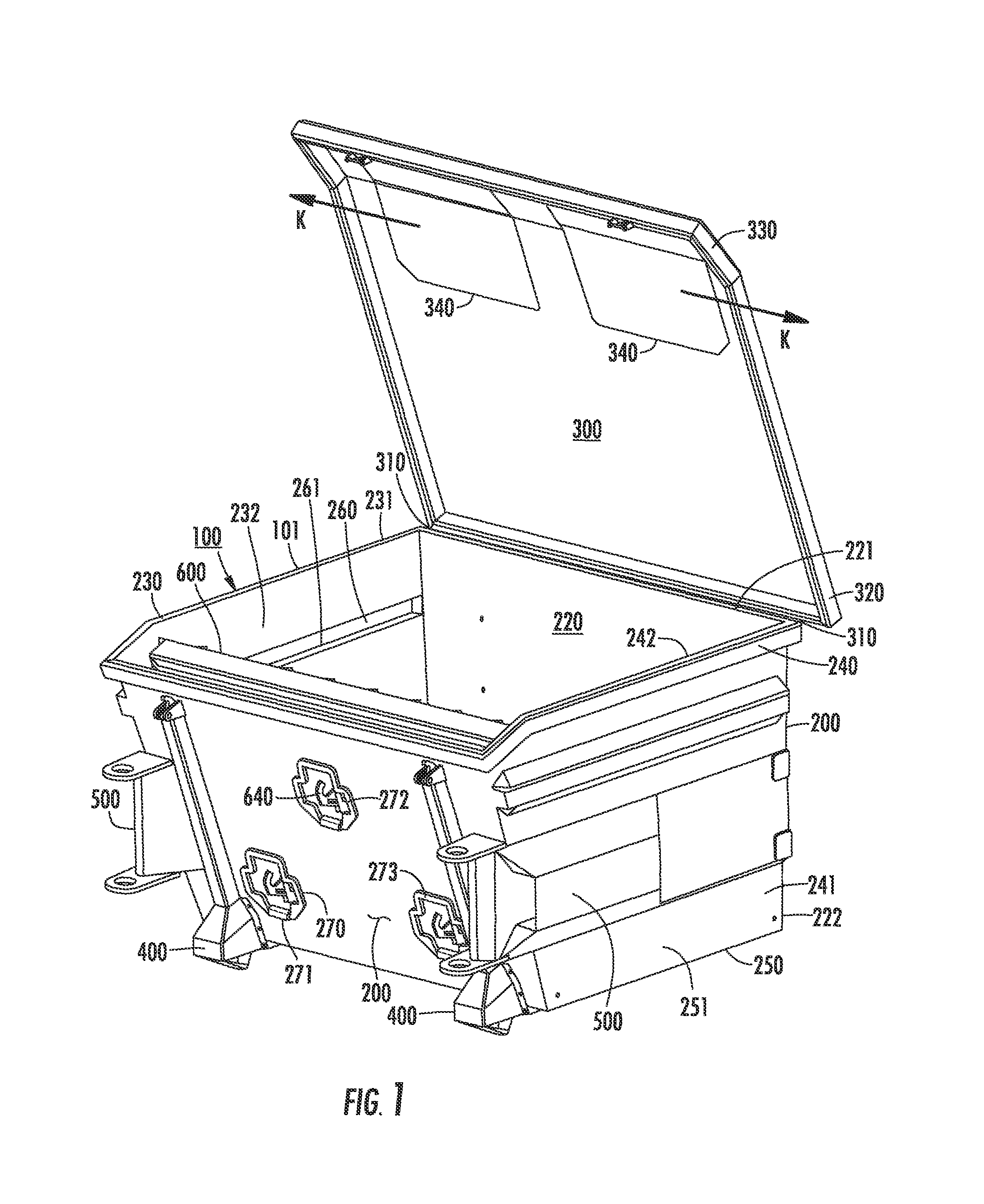
The invention is a trash receptacle that reduces the number of visits by large commercial vehicles. It uses a satellite vehicle with a power unit to collect and compact waste. The receptacle has a rigid outer housing with four main panels: a front panel, a back panel, a first side panel, and a second side panel. The front panel has one or more passageways. The outer housing is shaped with the front panel sloping outward and the first and second side panels being parallel to each other. In the back panel, there is a pivoting top door that attaches to the outer housing through a lock assembly. It also has a front side with one or more access doors for placing garbage. The outer housing may also have a deodorizer to improve the smell of the trash receptacle.

Problems solved by technology

Trash collection services that include routine scheduled emptying of dumpsters constitutes a significant expenditure for commercial and residential facilities and is typically billed on a per visit basis.
However, many times these trash dumpsters are less than full and the emptying schedule is excessive in that trash dumpsters could easily be filed with additional trash before emptying occurs.
Moreover, trash typically deposited in dumpsters is loose and expansive such that it takes up a significant volume, despite the fact the loose trash is mostly air.

Method used


Image

  • Trash receptacle for collecting and compacting waste and related method of use
  • Trash receptacle for collecting and compacting waste and related method of use
  • Trash receptacle for collecting and compacting waste and related method of use

Examples


Embodiment Construction

[0038]The present invention will now be described more fully hereinafter with reference to the accompanying drawings, in which preferred embodiments of the invention are shown. This invention may, however, be embodied in many different forms and should not be construed as limited to the embodiments set forth herein. Rather, these embodiments are provided so that this disclosure will be thorough and complete, and will fully convey the scope of the invention to those skilled in the art. Like numbers refer to like elements throughout.

Overall Trash Receptacle

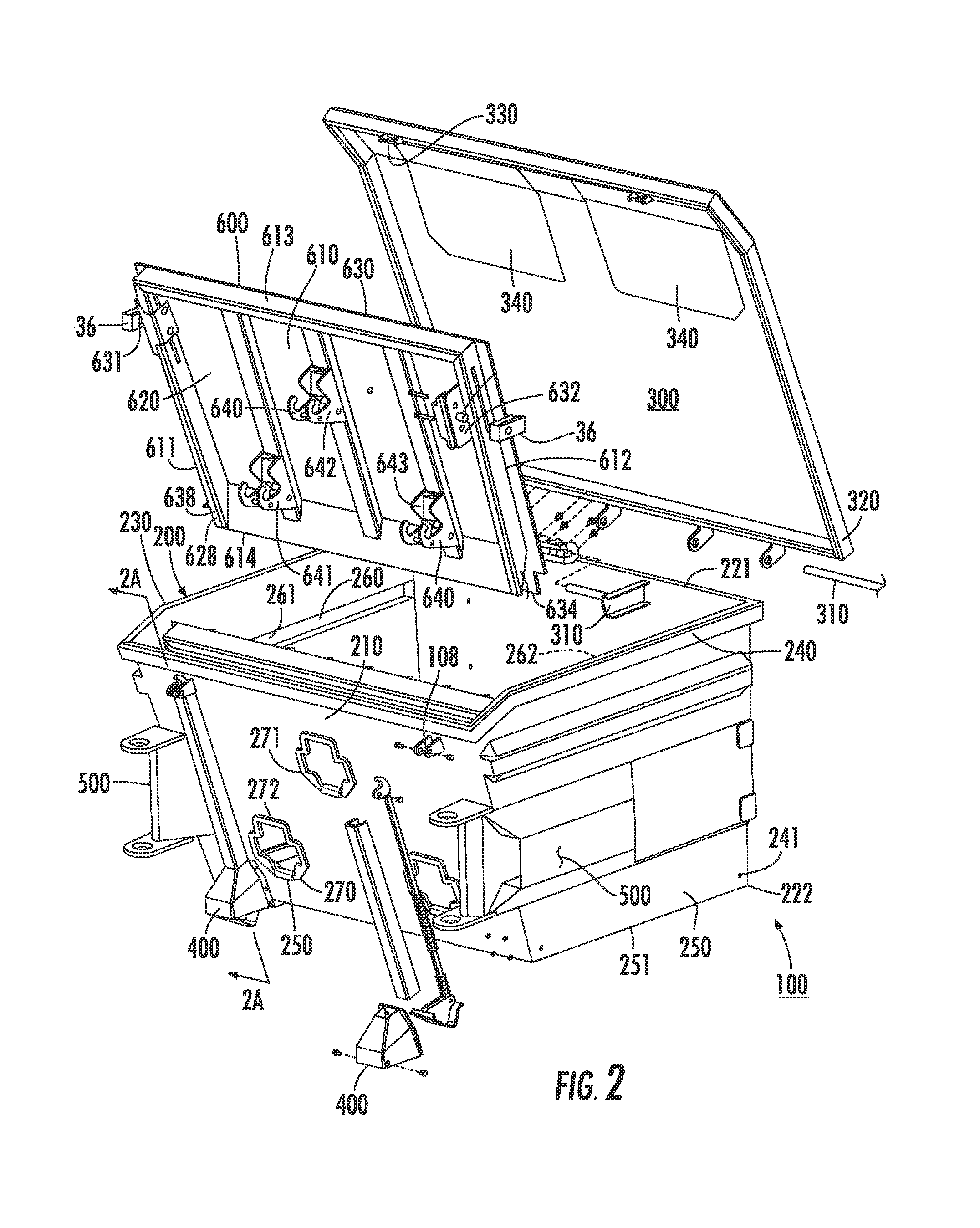
[0039]Both FIG. 1 and FIG. 2 illustrate, by way of example, one embodiment for the trash receptacle 100. First turning to FIG. 1, the trash receptacle 100 includes five primary components 101: a rigid outer housing 200, a pivoting top door 300, a corresponding lock assembly 400 (to open and lock the top door 300), a pair of engaging members 500 and a movable compaction ram 600 (positioned within the outer housing 200). Other additio...


PUM


Abstract

The invention is directed to a trash receptacle which includes engaging members that communicate with a satellite vehicle to compact trash. Such trash receptacle comprises a rigid outer housing having four main panels (front panel, a back panel, a first side panel and a second side panel). The front panel includes passageways. The four panels form a basin. Positioned on the back panel via a hinge is a pivoting top door that attaches through a lock assembly. The pivoting top door further includes access doors. A compaction ram, having ram connectors that exit the various passageways of the front panel, is positioned between the first and second side panels. The compaction ram includes one or more track guides capable of resting within tracks located on the first side panel and second side panel of the rigid housing. Such compaction ram may include a plurality of triangular beams having sharp edges.

Description

CROSS-REFERENCE TO RELATED APPLICATIONS[0001]This application is a Continuation-in-Part of U.S. patent application Ser. No. 12 / 264,102 entitled “System and Trash Receptacle for Collecting and Compacting Trash,” filed on Nov. 3, 2008, now U.S. Pat. No. 7,886,660, the contents of which are hereby incorporated by reference in its entirety.FIELD OF THE INVENTION[0002]This invention is directed to a trash receptacle for collecting and compacting trash. More specifically, the invention relates to a trash receptacle that includes a compaction ram sufficient to reduce the volume of garbage within a rigid outer housing so to decrease the number of times the trash receptacle must be emptied.BACKGROUND OF THE INVENTION[0003]Waste containers are devices for the temporary storage of waste which are usually manufactured of a metal, plastic or composite. Common terms used to identify waste containers include a rubbish bin, garbage can, trash can, dumpster, waste basket, or container bin. One preva...

Claims


Application Information

Patent Timeline
Patent Type & Authority Patents(United States)
IPC IPC(8): B30B13/00
CPCB30B9/3042B30B9/3021B30B9/3057B30B9/3032
Inventor SHERWOOD, CHRISTOPHER R.WALKER, DALE
Owner GOT GREEN
Learn More