
Angular velocity sensor element, angular velocity sensor and angular velocity sensor unit both using angular velocity sensor element, and signal detecting method for angular velocity sensor unit

a technology which is applied in the direction of acceleration measurement using interia force, turn-sensitive devices, instruments, etc., can solve the problems of poor stress to be transmitted to the detecting arm, low output sensibility of angular velocity sensor element, etc., to suppress the degradation of detection accuracy, improve the detection level, and increase the output sensibility

Active Publication Date: 2013-10-22
PANASONIC CORP
View PDF18 Cites 5 Cited by
  • Summary
  • Abstract
  • Description
  • Claims
  • Application Information

AI Technical Summary

Benefits of technology

[0016]The present invention provides an angular velocity sensor element with improvement in detection level and increase in output sensibility. Besides, the present invention suppresses degradation of detection accuracy of an angular velocity sensor unit.
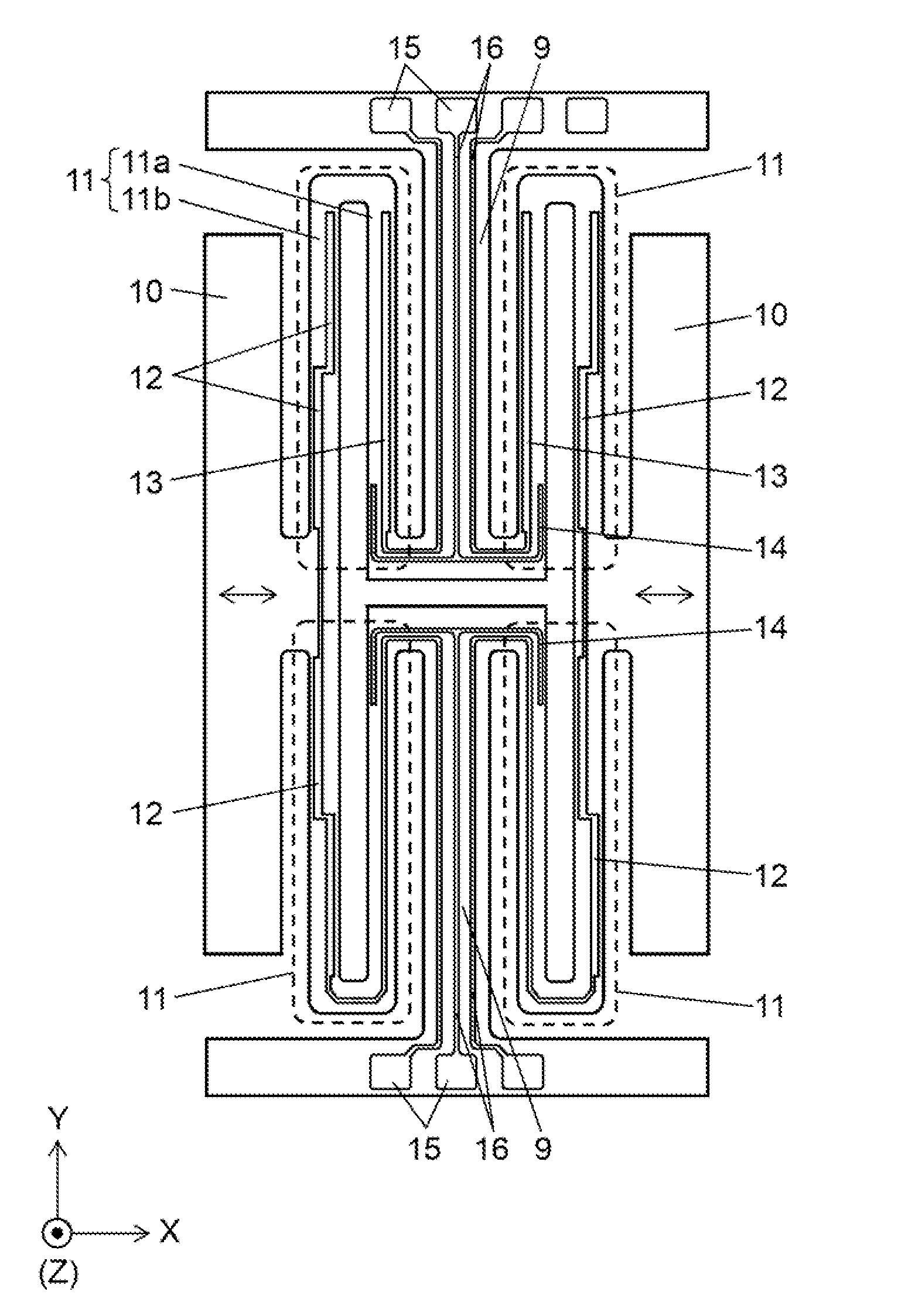
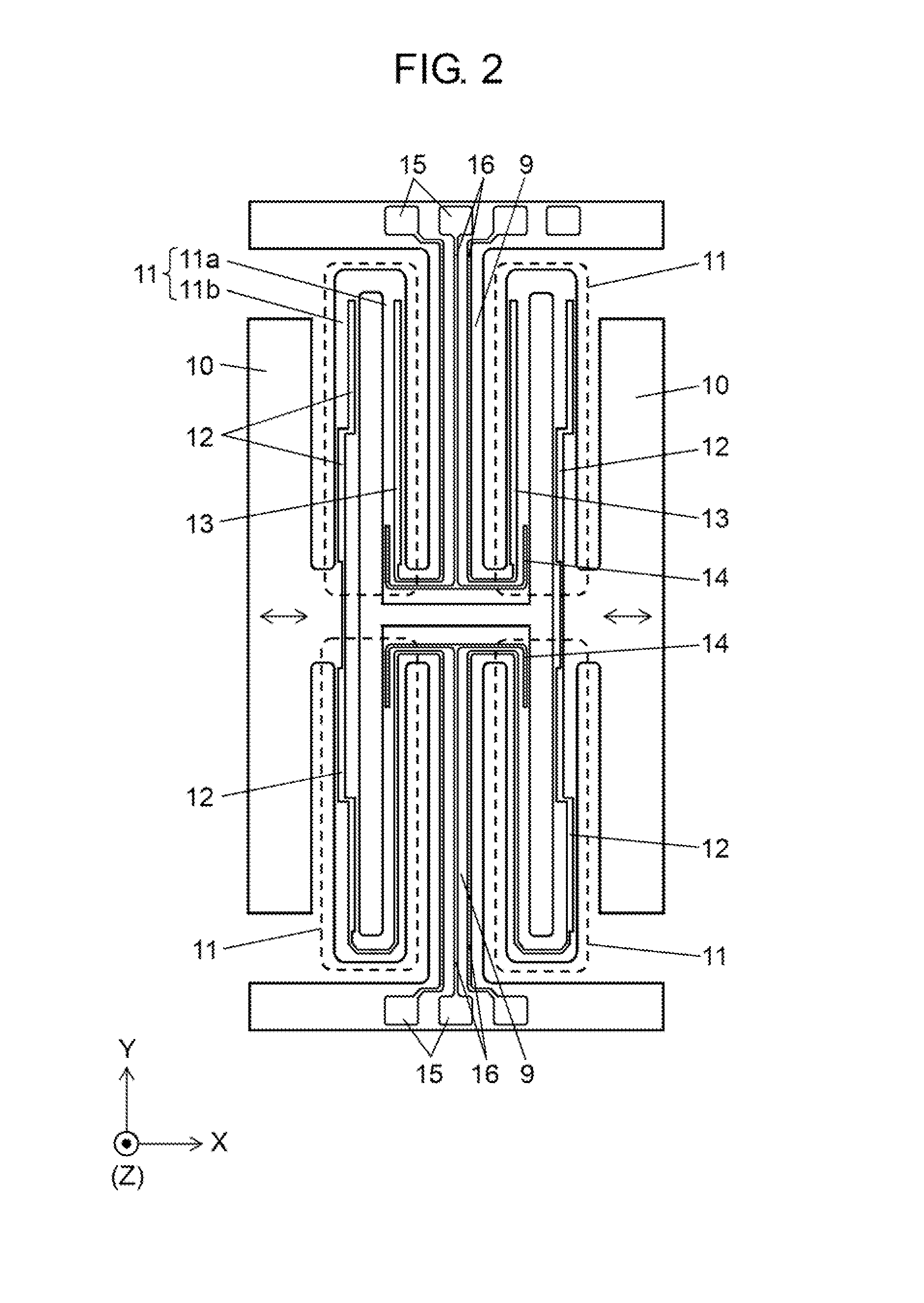
[0023]According to the structure above, the bend—disposed at the joint the detecting electrode vibrating body and the driving electrode vibrating body—works as a fulcrum point and allows both the vibrating bodies to have large deflection. This increases the Coriolis force occurred in the detecting electrode vibrating body, thereby increasing the level of the output signals from the detecting electrode of the detecting electrode vibrating body. As a result, the angular velocity sensor element enhances the output sensibility.
[0024]As an aspect of the present invention, an angular velocity sensor unit has a vibration sensor element for detecting angular velocity and a package containing an IC for controlling the sensor element. In the sensor element, a driving electrode, a monitoring electrode, and a sensing electrode are disposed on the driving arm. On the supporting arm that supports the driving arm, a correction electrode is disposed at a wiring electrode of a monitoring electrode. The correction electrode forms a correction signal caused by Z-axis vibration. That is, an unwanted signal formed in the monitoring electrode due to the Z-axis vibration is attenuated by the correction signal. The structure suppresses degradation of detection accuracy of the angular velocity sensor unit.

Problems solved by technology

It is therefore difficult to obtain the Coriolis force at around the base point of vibration of driving arm 1003, resulting in poor stress to be transmitted to detecting arm 1002a.
As a result, the angular velocity sensor element has low sensibility of output.

Method used


Image

  • Angular velocity sensor element, angular velocity sensor and angular velocity sensor unit both using angular velocity sensor element, and signal detecting method for angular velocity sensor unit
  • Angular velocity sensor element, angular velocity sensor and angular velocity sensor unit both using angular velocity sensor element, and signal detecting method for angular velocity sensor unit
  • Angular velocity sensor element, angular velocity sensor and angular velocity sensor unit both using angular velocity sensor element, and signal detecting method for angular velocity sensor unit

Examples


second exemplary embodiment

[0070]Hereinafter, the structure of an angular velocity sensor of the second exemplary embodiment will be described with reference to the accompanying drawings.

[0071]FIG. 10 is a top view showing an angular velocity sensor element in accordance with the second exemplary embodiment of the present invention. FIG. 11 is a sectional view showing a detecting electrode vibrating body and a driving electrode vibrating body of the angular velocity sensor element in accordance with the second exemplary embodiment of the present invention. FIG. 12 is a sectional view showing the detecting electrode vibrating body and a monitoring electrode vibrating body of the angular velocity sensor element in accordance with the second exemplary embodiment of the present invention.

[0072]In FIG. 10 through FIG. 12, the structure has first holding section 221 and second holding section 225, which are made of crystal and formed into a T shape. They are located on the same level. On the top surface of holding ...

third exemplary embodiment

[0089]Hereinafter, an angular velocity sensor unit of the present invention will be described with reference to the accompanying drawings.

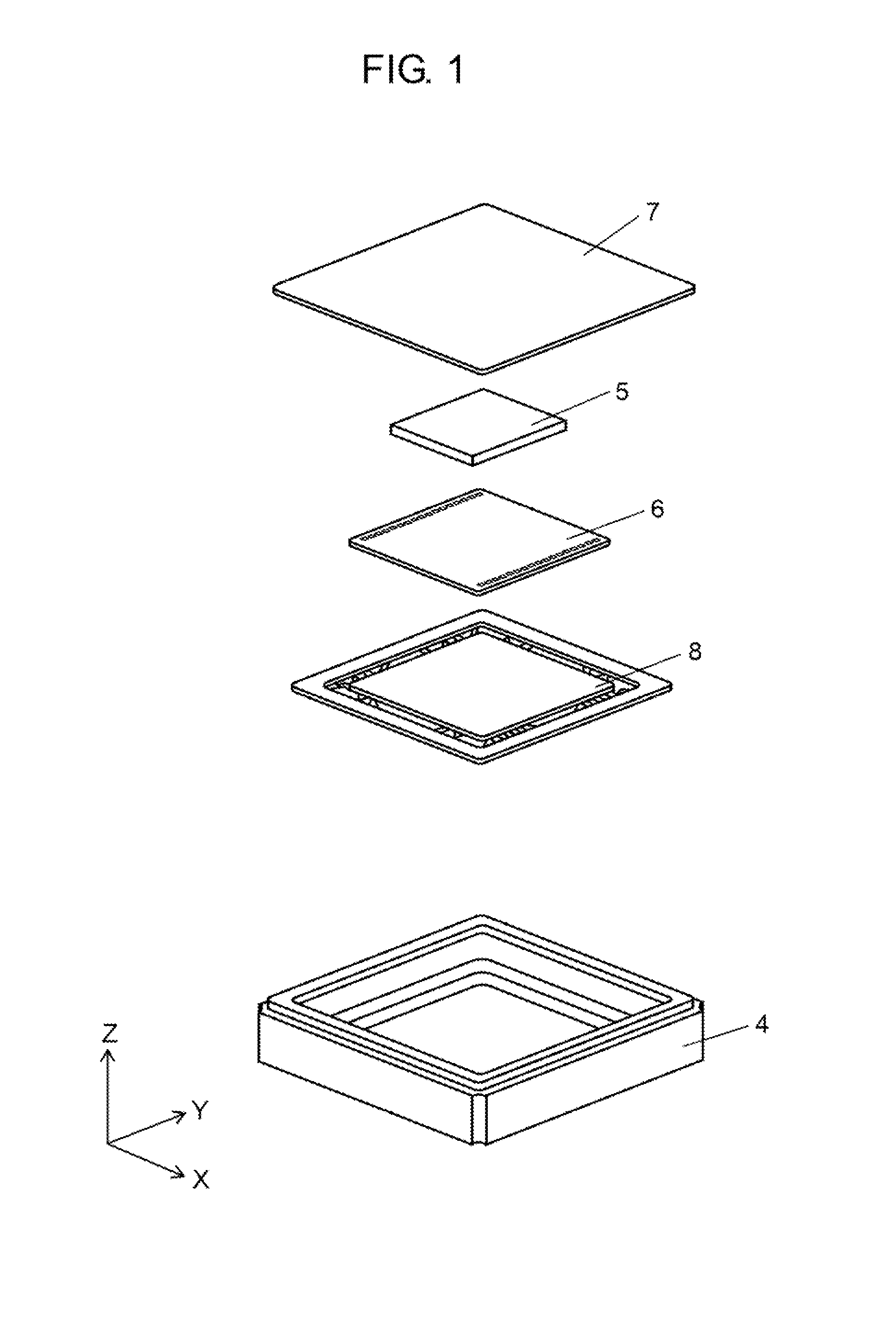
[0090]FIG. 15 is an exploded perspective view showing an angular velocity sensor unit in accordance with the third exemplary embodiment of the present invention. In FIG. 15, package 303 contains vibration angular velocity sensor element 301 for detecting angular velocity and IC 302. IC 302 has a driving control circuit that applies a driving signal to angular velocity sensor element 301 and a detecting circuit that processes a detecting signal fed from sensor element 301. The opening of package 303 is covered with lid 314.

[0091]FIG. 16 is a top view showing the sensor element of the angular velocity sensor unit in accordance with the third exemplary embodiment of the present invention. In FIG. 16, sensor element 301 has external connection sections 315, supporting arms 316, weighting sections 317, and a pair of driving arms 305. Each of supporting...


PUM


Abstract

The angular velocity sensor of the present invention has one end connected to holding section and the other end connected to weighting section. According to the angular velocity sensor, driving arm has a dog-leg structure of arms extending in a direction perpendicular to a connecting direction of holding section and weighting section.

Description

[0001]This application is a U.S. national phase application of International Application PCT / JP2009 / 005177, filed Oct. 6, 2009.BACKGROUND OF THE INVENTION[0002]I. Technical Field[0003]The present invention relates to an angular velocity sensor element used for electronic equipment, an angular velocity sensor having the element, and an angular velocity sensor unit. It also relates to a method of detecting a signal of the angular velocity sensor element.[0004]II. Description of the Related Art[0005]FIG. 23 is a top view showing a conventional angular velocity sensor element. In FIG. 23, a pair of arms 1002a and a pair of arms 1002b extend in a crosswise direction from holding section 1001 as the center. In each pair, the arms are symmetrically disposed. The pair of arms 1002a is detecting arm 1002a, whereas the pair of arms 1002b is supporting arm 1002b. Driving arm 1003 is disposed on the tip of supporting arm 1002b. When driving arm 1003 is vibrated in the directions indicated by th...

Claims


Application Information

Patent Timeline
Patent Type & Authority Patents(United States)
IPC IPC(8): G01C19/56
CPCG01C19/574
Inventor KOBAYASHI, YASUNOBUKAWAI, TAKASHIMITANI, TOMOHIROASHIMORI, YOUHEI
Owner PANASONIC CORP
Learn More