Safety controller and method for controlling an automated installation

a safety controller and automated installation technology, applied in the direction of electric controllers, program control, instruments, etc., can solve the problems of considerable complexity in development and manufacture, hazard to humans or material goods during operation, etc., and achieve the effect of improving the handling capability

Active Publication Date: 2013-10-15
PILZ (COMPANY)
View PDF19 Cites 8 Cited by
  • Summary
  • Abstract
  • Description
  • Claims
  • Application Information

AI Technical Summary

Benefits of technology

[0009]It is therefore an object of the present invention to provide a safety controller and a method for controlling an automated installation with an improved capability of dealing with undesired situations, such as malfunctions, errors or faulty components.
[0010]It is another object to provide a safety controller and a method which allow convenient and flexible fault analysis on the basis of diagnosis information.
[0011]It is yet another object to provide a safety controller and a method which allow to react to operational process and systems states in a fast and flexible manner.

Problems solved by technology

Such sensors are used for safeguarding a machine, for example, which presents a hazard to humans or material goods during operation.
Extremely high demands are therefore made of safety controllers in terms of their own fail safety, which results in considerable complexity for development and manufacture.

Method used


Image

  • Safety controller and method for controlling an automated installation
  • Safety controller and method for controlling an automated installation
  • Safety controller and method for controlling an automated installation

Examples


Embodiment Construction

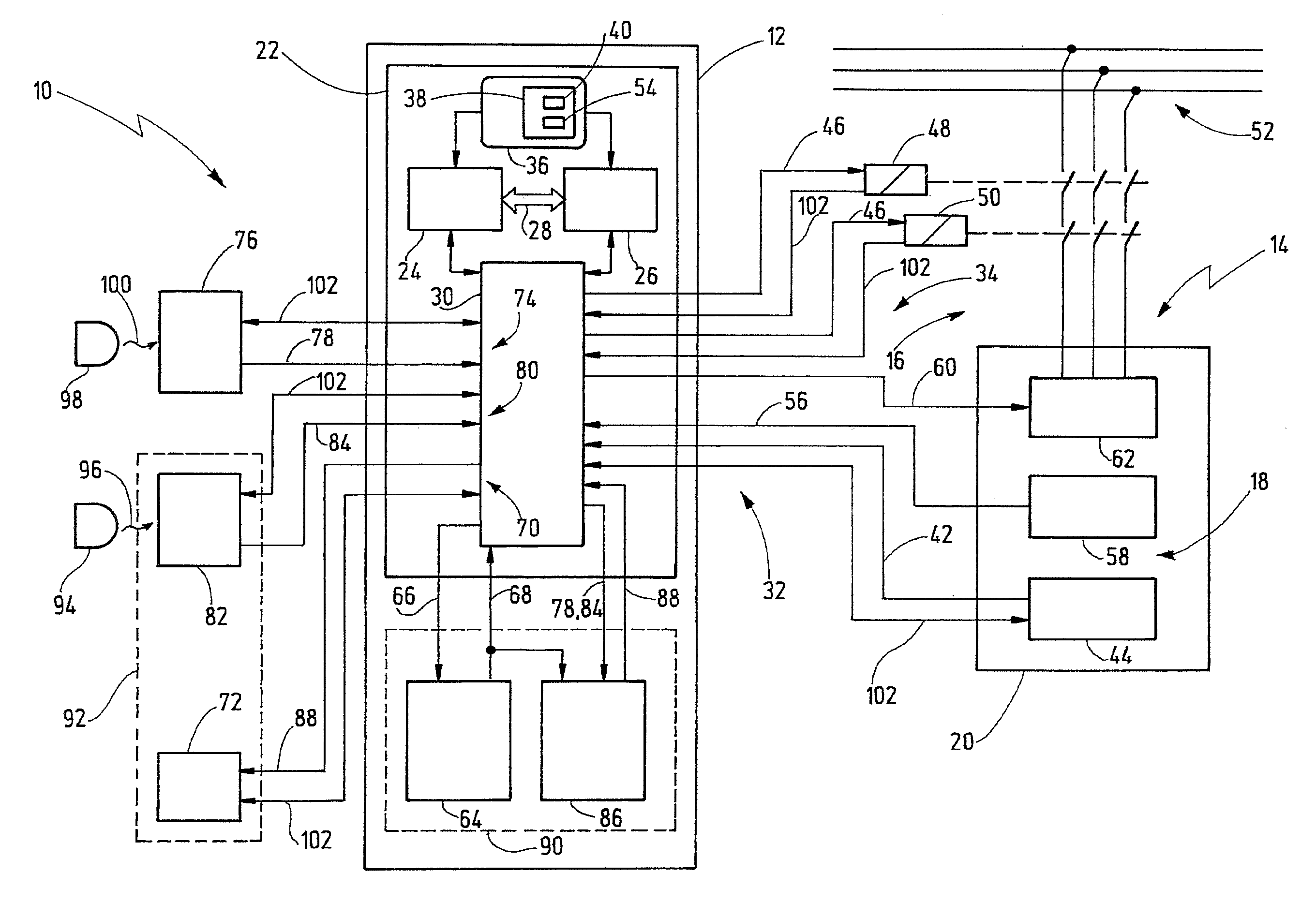
[0039]FIG. 1 shows a safety circuit, denoted as a whole by reference numeral 10, which comprises a safety controller 12 designed to control an installation 14. The installation 14 comprises a plurality of actuators 16 and a plurality of sensors 18. As an example, a load 20 is shown, which load is a part of the installation 14 and may be a robot, for instance.

[0040]The safety controller 12 comprises a control unit 22. The control unit 22 is of two-channel redundant design in order to achieve the required fail safety for controlling safety-critical processes. As a representation of the two-channel design, FIG. 1 shows two separate processors 24, 26 which are connected to one another by means of a bidirectional communication interface 28 in order to be able to monitor one another and to interchange data. Preferably, the two channels of the control unit 22 and the two processors 24, 26 are diverse, i.e. of different design to one another, in order to avoid systematic faults.

[0041]Refere...


PUM


Abstract

A safety controller for controlling an automated installation which has a plurality of sensors and a plurality of actuators, comprises a control unit to which a plurality of control input signals are supplied by the sensors. The control unit produces a plurality of control output signals in an automatic mode on the basis of the control input signals in accordance with a user program running in said control unit. The plurality of control output signals is used to actuate the plurality of actuators. The safety controller also has a diagnosis evaluation unit to which a number of diagnoses input signals are supplied. The diagnosis evaluation unit takes the diagnosis input signals as a basis for ascertaining which of a plurality of operating states is present at a defined instant of time. The diagnosis evaluation unit produces an operating state data record which represents an ascertained operating state. The safety controller also has an interface for a display unit in order to display diagnosis reports. The operating state data record includes a plurality of diagnosis data and a Boolean status indicator. The control unit actuates at least one actuator on the basis of the Boolean status indicator contained in the operating state data record.

Description

CROSS REFERENCES TO RELATED APPLICATIONS[0001]This application is a continuation of international patent application PCT / EP2009 / 08262 filed on Nov. 20, 2009 designating the U.S., which international patent application has been published in German language and claims priority from German patent application DE 10 2008 060 011.3 filed on Nov. 25, 2008. The entire contents of these priority applications are incorporated herein by reference.BACKGROUND OF THE INVENTION[0002]The present invention relates to a safety controller and a method for controlling an automated installation which comprises a plurality of sensors and a plurality of actuators.[0003]A safety controller in terms of the present invention is an apparatus or an arrangement, which receives input signals provided by sensors and produces output signals therefrom by means of logic combinations and sometimes further signal or data processing steps. The output signals can be supplied to actuators, which then effect specific acti...

Claims


Application Information

Patent Timeline
Patent Type & Authority Patents(United States)
IPC IPC(8): G05B9/02G05B11/01
CPCG05B19/0425G05B23/0251G05B2219/31437G05B2219/32414
Inventor EHRHART, HELMUTREUSCH, MATTHIAS
Owner PILZ (COMPANY)
Why Eureka
Try Eureka