
Method and device for determining the actuation position of an adjusting element of a motor vehicle

a technology for determining the actuation position and motor vehicles, which is applied in the direction of door/window fittings, wing accessories, instruments, etc., can solve the problems of difficult handling and the danger of immediate miscounting of hall-effect sensors, and achieve the effect of simple and suitabl

Inactive Publication Date: 2013-10-08
BROSE FAHRZEUGTEILE GMBH & CO KG HALLSTADT (DE)
View PDF7 Cites 9 Cited by
  • Summary
  • Abstract
  • Description
  • Claims
  • Application Information

AI Technical Summary

Benefits of technology

This approach enhances the resistance to counting errors and provides reliable determination of the actuation position, ensuring accurate position detection and preventing miscounting, especially after the Hall-effect sensor has been inactive.

Problems solved by technology

Independently of the sensor concept, but in particular when a CMOS Hall-effect sensor is used in which a level change takes place when the upper threshold is positively exceeded and when the lower threshold is negatively exceeded, and a specific level, for example a high level, is prescribed within the hysteresis, states can arise that can lead to miscounting.
Conditions leading to miscounting resulting from shifting of the switching thresholds of the Hall-effect sensor due to its self-heating or cooling, or a (slight) reverse rotation of the ring magnet subsequent to execution of a stop function of the electric motor, are extremely difficult to handle in this context.
The danger of immediate miscounting of the Hall-effect sensor exists, in particular, after shutoff of the Hall-effect sensor or after restarting of a drive unit having the electric motor and ring magnet from an inactive phase (quiescent phase) when the switching thresholds have shifted as a result of temperature or operating conditions, and one pulse too many or too few is counted as a result.

Method used


Image

  • Method and device for determining the actuation position of an adjusting element of a motor vehicle
  • Method and device for determining the actuation position of an adjusting element of a motor vehicle
  • Method and device for determining the actuation position of an adjusting element of a motor vehicle

Examples


Embodiment Construction

[0035]Corresponding parts are labeled with the same reference symbols in all figures.

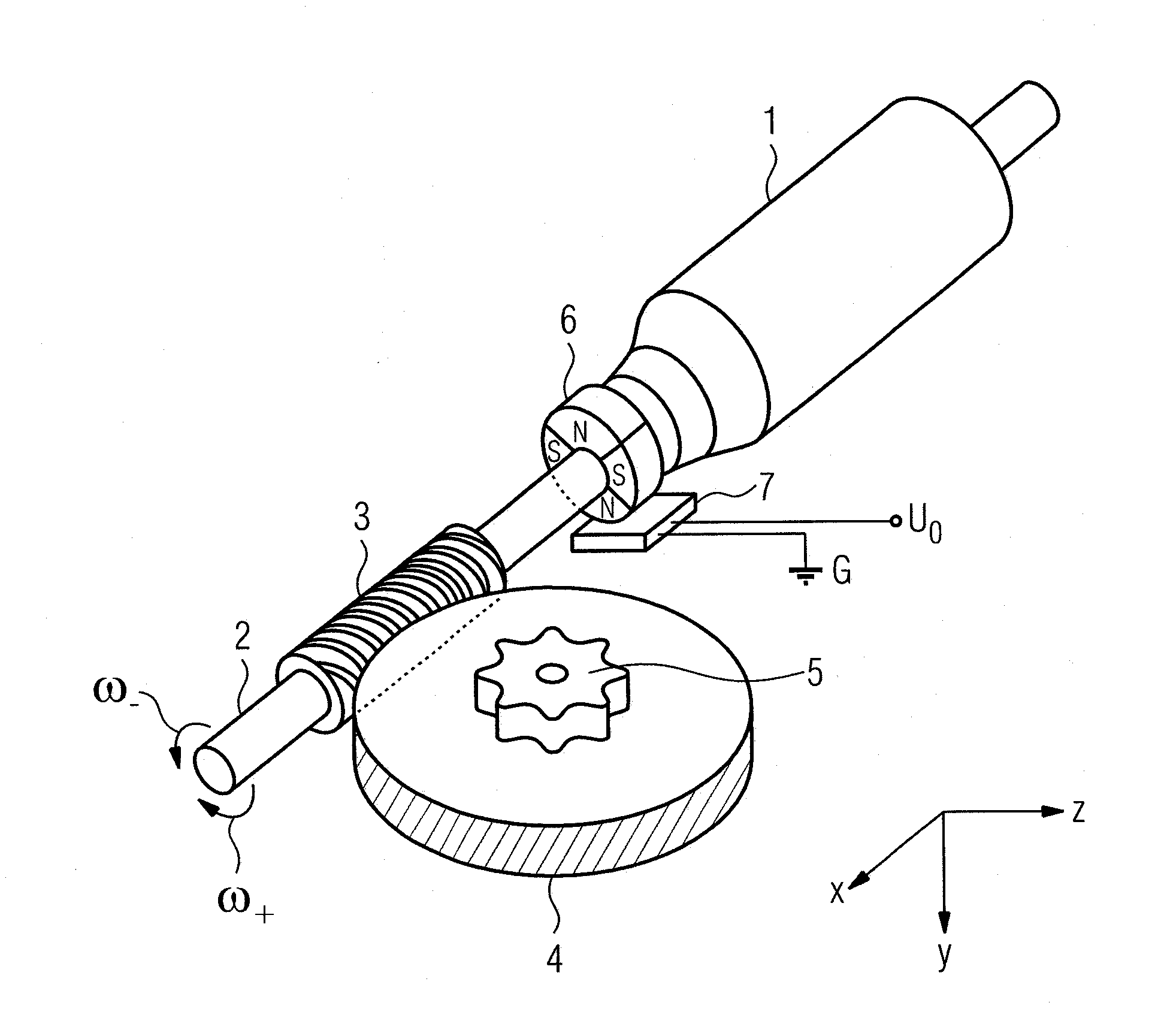
[0036]FIG. 1 shows an electric motor drive 1, for example a power window drive, of a motor vehicle with a drive shaft 2 bearing the rotor or armature (not shown) of an electric motor and with a worm drive that has a worm 3 located on the drive shaft 2 and a helical-cut worm gear 4 that meshes therewith. Due to the gear ratio between the worm 3 and the worm gear 4, the latter's rotational speed is reduced relative to the rotational speed ω of the drive shaft 2, while the torque is increased. While the drive shaft 2 rotates about the x axis shown, the worm gear 4, which lies in a plane parallel to the xz plane, rotates about an axis of rotation y that is perpendicular thereto.

[0037]The worm drive 3, 4 is mechanically coupled by means of a gear attachment 5 in a manner not shown in detail, for example a cable drum and a sheathed cable, to a carrier—often guided by rails—of a window as an adjusting elem...


PUM


Abstract

In order to determine the actuation position of a motor-driven adjusting element of a motor vehicle, a Hall-effect sensor is located in a rotatable magnetic field, wherein a periodic change in the magnetic flux density sensed by the Hall-effect sensor is converted into a binary pulse train in that a pulse transition takes place when an upper switching threshold is positively exceeded and when a lower switching threshold separated from the upper switching threshold by a hysteresis is negatively exceeded. The hysteresis is reduced following an inactive phase of the Hall-effect sensor during which the magnetic field was stationary and / or the Hall-effect sensor was deactivated, if the magnetic flux density at the start of the inactive phase has exceeded the upper switching threshold by no more than a predefined tolerance range.

Description

[0001]This nonprovisional application claims priority under 35 U.S.C. §119(a) to German Patent Application No. DE 10 2009 034 664.3, which was filed in Germany on Jul. 24, 2009, and which is herein incorporated by reference.BACKGROUND OF THE INVENTION[0002]1. Field of the Invention[0003]The invention relates to a method for determining an actuation position of a motor-driven adjusting element of a motor vehicle. It further relates to an actuator operating according to the method.[0004]2. Description of the Background Art[0005]In a modern motor vehicle, a number of actuators or adjusting elements operated by electric motors are usually present. These include, for example, an electric window regulator, an electric seat adjuster, and a device for motorized adjustment of a vehicle door, trunk lid, sunroof, or convertible top.[0006]During an actuation process of such an adjusting element, it is frequently necessary to precisely move to a desired end position. A precise knowledge of the a...

Claims


Application Information

Patent Timeline
Patent Type & Authority Patents(United States)
IPC IPC(8): G01B7/30
CPCG01D5/2451E05F15/697G01D5/2448E05Y2400/334E05Y2900/55
Inventor SEMINETH, MARCOTHOMANN, CHRISTIANSCHINDHELM, THOMAS
Owner BROSE FAHRZEUGTEILE GMBH & CO KG HALLSTADT (DE)
Learn More