
Charging circuit with function of avoiding battery pulling down voltage output from charging device and charging method thereof

a charging circuit and battery technology, applied in electric vehicles, electric power, transportation and packaging, etc., can solve problems such as inconvenience, the main control microchip of the mobile phone may not be able to provide startup capability,

Active Publication Date: 2013-10-08
SHENZHEN FUTAIHONG PRECISION IND CO LTD +1
View PDF12 Cites 38 Cited by
  • Summary
  • Abstract
  • Description
  • Claims
  • Application Information

AI Technical Summary

Benefits of technology

The patent describes how a portable electronic device like a mobile phone can tell when its battery is low on power and will display a message to let you know. You can recharge the battery using a charger that comes with the device or a USB interface charger. The technical effect is to improve the device's functionality and make it last longer by providing a convenient way to recharge it.

Problems solved by technology

When voltage of a battery of a portable electronic device, such as a mobile phone is insufficient, the mobile phone can display a “lower power” notification until the battery is exhausted.
However, since a charging current can be about 1 A at initial charging, the battery may pull down voltage output from the charging devices.
At this time, a main control microchip of the mobile phone may not be able to provide startup capability due to the reduced voltage.
Thus, inconvenience is caused.

Method used


Image

  • Charging circuit with function of avoiding battery pulling down voltage output from charging device and charging method thereof
  • Charging circuit with function of avoiding battery pulling down voltage output from charging device and charging method thereof
  • Charging circuit with function of avoiding battery pulling down voltage output from charging device and charging method thereof

Examples


Embodiment Construction

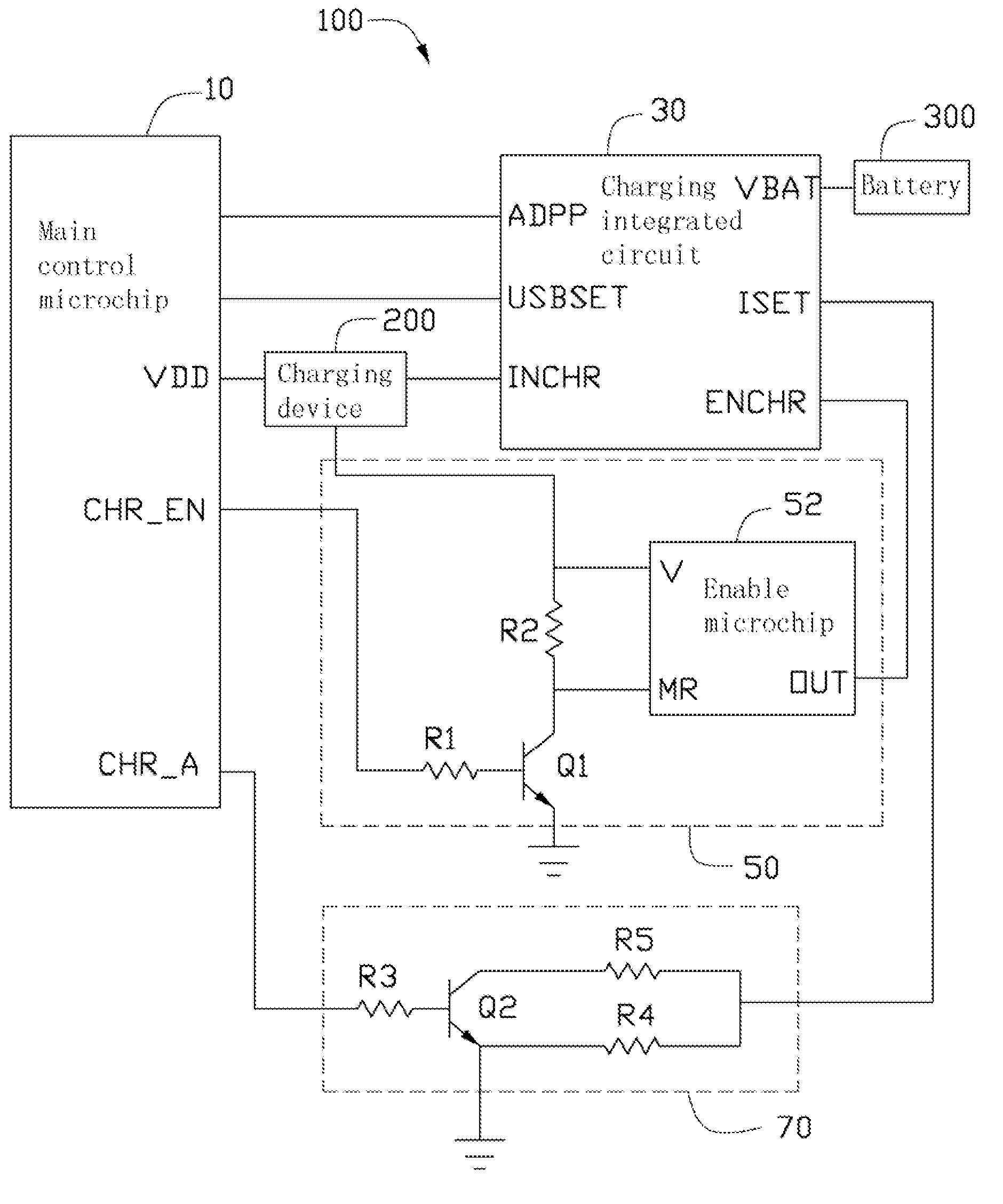
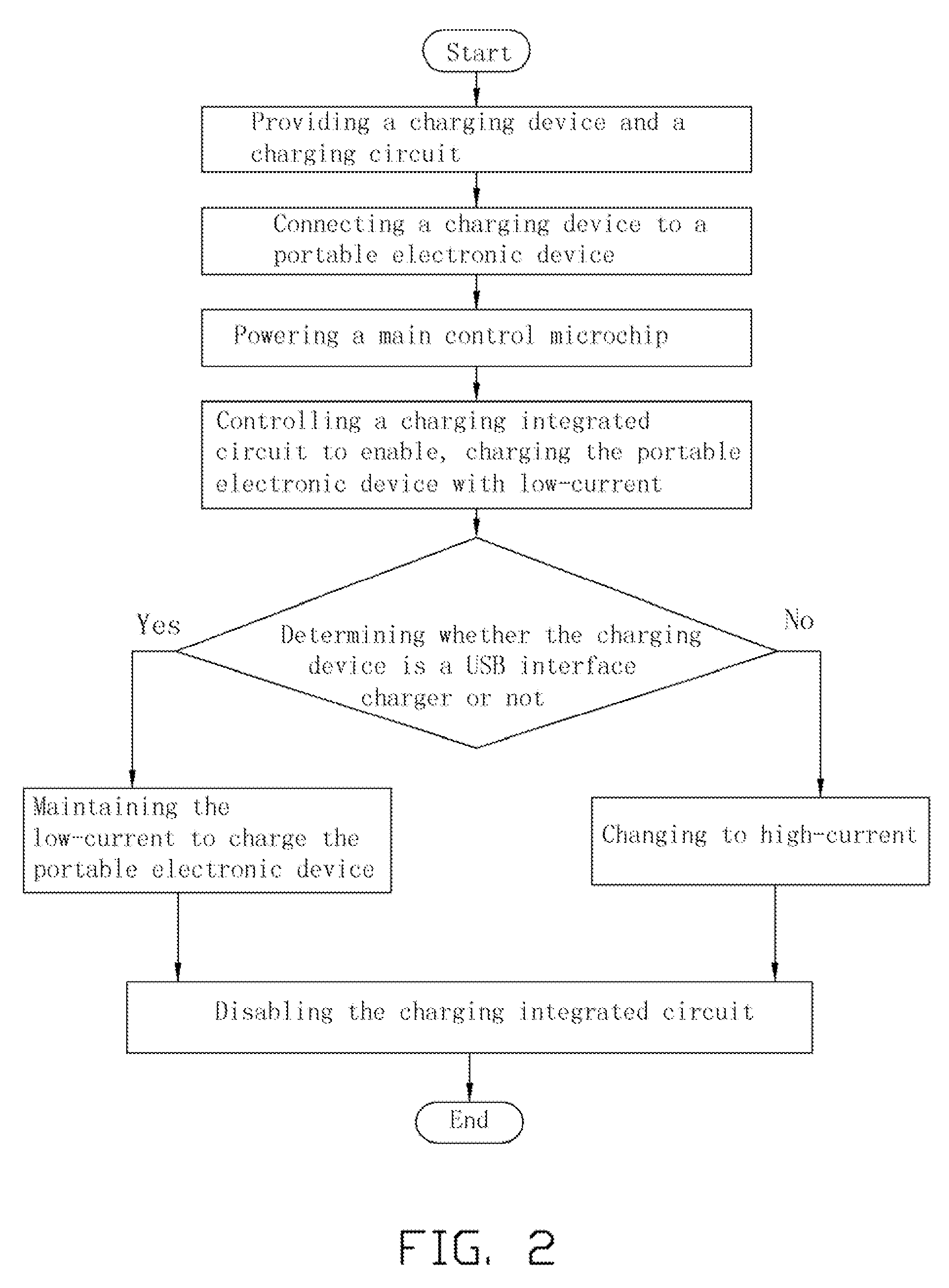
[0010]FIG. 1 shows a charging circuit 100, according to an exemplary embodiment. The charging circuit 100 can be used in a mobile phone, a personal digital assistant (PDA) or other portable electronic device that is capable of charging a battery 300 via a charging device 200. The charging device 200 can be a mobile phone charger or a USB interface charger, for example.

[0011]The charging circuit 100 includes a main control microchip 10, a charging integrated circuit 30, an enable circuit 50, and a current control circuit 70.

[0012]The main control microchip 10, capable of executing startup programs, includes a power-on pin VDD, a microchip enable pin CHR_EN, and a current control pin CHR_A. The power-on pin VDD is electronically connected to the charging device 200 to obtain power for the main control microchip 10. The microchip enable pin CHR_EN is operable to output a high voltage signal (e.g., logic 1) to the enable circuit 50 when the charging device 200 is connected to the portab...


PUM


Abstract

A charging circuit includes a main control microchip, a charging integrated circuit, and a current control circuit. The main control microchip includes a power-on pin connected to a charging device. The charging integrated circuit comprises a power input pin and a current limit pin, wherein the power input pin is connected to the charging device, and the charging integrated circuit is capable of limiting current. The current control circuit comprises a transistor, a first current limiting resistor and a second current limiting resistor, a base of the transistor is connected to the main control microchip, the first current limiting resistor is connected between the current limit pin and ground, and the second current limiting resistor is connected between the current limit pin and a collector of the transistor, the main control microchip is operable to output control signals to enable or disable the transistor.

Description

BACKGROUND[0001]1. Technical Field[0002]The disclosure generally relates to charging circuits, and more particularly relates to a charging circuit used in a portable electronic device and a charging method thereof.[0003]2. Description of the Related Art[0004]When voltage of a battery of a portable electronic device, such as a mobile phone is insufficient, the mobile phone can display a “lower power” notification until the battery is exhausted. Recharging of the battery can be performed by a mobile phone charger or USB interface charger.[0005]However, since a charging current can be about 1 A at initial charging, the battery may pull down voltage output from the charging devices. At this time, a main control microchip of the mobile phone may not be able to provide startup capability due to the reduced voltage. Thus, inconvenience is caused.[0006]Therefore, there is room for improvement within the art.BRIEF DESCRIPTION OF THE DRAWINGS[0007]Many aspects of an exemplary charging circuit...

Claims


Application Information

Patent Timeline
Patent Type & Authority Patents(United States)
IPC IPC(8): H02J7/00
CPCH02J7/045H02J2007/0062H02J7/04H02J7/007182H02J7/00
Inventor WU, HAI-ZHOU
Owner SHENZHEN FUTAIHONG PRECISION IND CO LTD
Learn More