
Insertion auxiliary implement

a technology of auxiliary implements and implements, applied in the field of insertion auxiliary implements, can solve problems such as the discomfort of patients increasing

Active Publication Date: 2013-10-08
OLYMPUS CORP
View PDF34 Cites 878 Cited by
  • Summary
  • Abstract
  • Description
  • Claims
  • Application Information

AI Technical Summary

Benefits of technology

[0005]An insertion auxiliary implement of the present invention includes: a tubular part into which a flexible endoscope insertion part which is insertable into a body cavity, and one of a treatment tool and a channel into which the treatment tool is insertable, are insertable; and a sealing member which has through holes for supporting the endoscope insertion part and one of the treatment tool and the channel in the tubular part, and which airtightly and movably contacts each of a periphery of the endoscope insertion part, a periphery of the treatment tool or a periphery of the channel, and an inner surface of the tubular part, and thereby maintains airtightness between a distal end and a proximal end inside the tubular part.

Problems solved by technology

Furthermore, depending on the operations, there are cases in which the endoscope is inserted and extracted repeatedly, and in such a case, the discomfort to the patient becomes larger.

Method used


Image

  • Insertion auxiliary implement
  • Insertion auxiliary implement
  • Insertion auxiliary implement

Examples


first embodiment

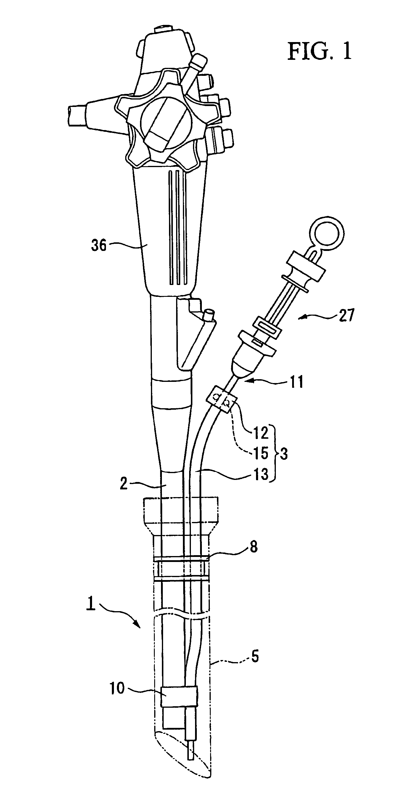
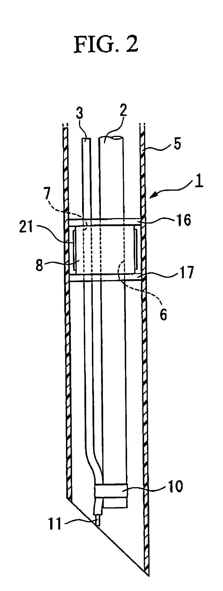
[0034]A first embodiment according to the present invention will be explained below with reference to FIGS. 1 to 12.

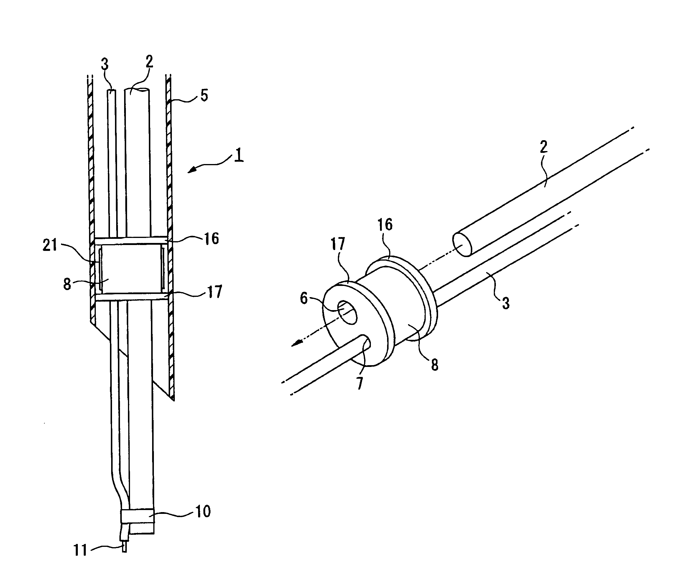
[0035]As shown in FIGS. 1 to 3, an insertion auxiliary implement 1 of the present invention includes: a tubular part 5 in which a flexible endoscope insertion part 2 which is inserted in a body cavity, and an external channel (channel) 3 are inserted; a sealing member 8 which has through holes 6 and 7 for supporting the endoscope insertion part 2 and the external channel 3 within the tubular part 5, and which airtightly and movably contacts each of a periphery of the endoscope insertion part 2, a periphery of the external channel 3, and an inner surface of the tubular part 5, and thereby maintains airtightness between a distal end and a proximal end inside the tubular part 5; and a fastener 10 which fastens the sealing member 8, the endoscope insertion part 2, and the external channel 3 together, after inserting the endoscope insertion part 2 and the external channel 3...

second embodiment

[0067]Next, the present invention will be explained with reference to FIGS. 13 and 14.

[0068]Moreover, in the following explanation, the same reference numerals will be used for the same components explained in the above-mentioned first embodiment.

[0069]An insertion auxiliary implement 38 according to the present embodiment differs from the insertion auxiliary implement 1 according to the above-mentioned first embodiment in the points in which: a sealing member 40 is fixed to the inner surface at the proximal end side of the tubular part 5; the ligation apparatus 11 is directly held by the sealing member 40 without the external channel 3; and a slit 40A is provided between the through holes 41 and 6.

[0070]The through hole 41 has an internal shape which fits with the outer shape of the guide tube 26 of the ligation apparatus 11 when they are seen in the cross sectional view which is vertical to an axis of the guide tube 26, thereby the through hole 41 can support the guide tube 26. In...


PUM


Abstract

An insertion auxiliary implement of the present invention includes: a tubular part into which a flexible endoscope insertion part which is insertable into a body cavity, and one of a treatment tool and a channel into which the treatment tool is insertable, are insertable; and a sealing member which has through holes for supporting the endoscope insertion part and one of the treatment tool and the channel in the tubular part, and which airtightly and movably contacts each of a periphery of the endoscope insertion part, a periphery of the treatment tool or a periphery of the channel, and an inner surface of the tubular part, and thereby maintains airtightness between a distal end and a proximal end inside the tubular part.

Description

BACKGROUND OF THE INVENTION[0001]Priority is claimed on Japanese Patent Application No. 2003-397377, filed Nov. 27, 2003, the contents of which are incorporated herein by reference.FIELD OF THE INVENTION[0002]The present invention relates to an insertion auxiliary implement which is used for inserting an endoscope, etc., into a body cavity.DESCRIPTION OF RELATED ART[0003]Endoscopes are widely used for purposes of diagnosis and treatment of tumors in the stomach, esophagus, etc., and diseases in the alimentary canal such as varicose veins. However, when inserting an endoscope insertion part, for example, into the esophagus via the mouth, an operator is required to be skilled in order to insert it with less pain for the patient. Furthermore, depending on the operations, there are cases in which the endoscope is inserted and extracted repeatedly, and in such a case, the discomfort to the patient becomes larger.[0004]Therefore, a tubular shaped insertion auxiliary implement is proposed ...

Claims


Application Information

Patent Timeline
Patent Type & Authority Patents(United States)
IPC IPC(8): A61B1/00A61B1/04A61M5/178A61B1/01A61B1/273A61B17/28A61B17/34A61M13/00
CPCA61B1/00154A61B1/273A61B1/00066A61B1/00137A61B1/0014A61B17/29A61B17/3462A61B17/3498A61B2017/00296A61B2017/3419A61B2017/3441A61M13/003
Inventor TAKEMOTO, SHOTARO
Owner OLYMPUS CORP
Learn More