
Lamp base with upgradeable recharging port and method

a technology of rechargeable recharging port and rechargeable battery, which is applied in the direction of emergency power supply arrangement, coupling device connection, lighting support device, etc., can solve the problem that travelers with any of a variety of available portable electronic devices often no longer have the option of carrying spare replacement alkaline batteries

Inactive Publication Date: 2013-10-01
PATEL BHARAT
View PDF11 Cites 28 Cited by
  • Summary
  • Abstract
  • Description
  • Claims
  • Application Information

AI Technical Summary

Benefits of technology

The invention is a lamp base that can be used to recharge portable electronic devices using a standard cigarette lighter receptacle. The lamp base includes a voltage and current conversion circuit that converts standard household voltage and current into standard automotive voltage and current. The lamp base also includes a replaceable snap-lock USB adapter plug that can be easily replaced to provide different USB voltage and current. The lamp base system also includes a direct circuit for connecting the standard household voltage and current to the light fixture, and an automotive cigarette lighter receptacle for operating and recharging the portable electronic device. The technical effect of the invention is to provide a convenient and flexible way to recharge portable electronic devices in a vehicle.

Problems solved by technology

Travelers with any of a variety of available portable electronic devices often no longer have the option to carry spare replacement alkaline batteries, but instead travel with the recharging cords or recharging devices specially adapted for each of the portable electrical devices being carried by the traveler.

Method used


Image

  • Lamp base with upgradeable recharging port and method
  • Lamp base with upgradeable recharging port and method
  • Lamp base with upgradeable recharging port and method

Examples


Embodiment Construction

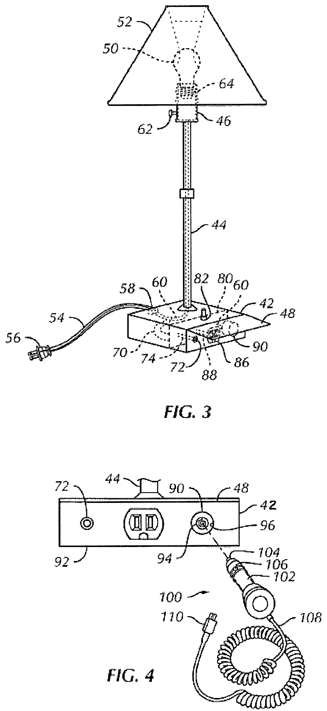
[0029]One or more embodiments of the invention will be described with reference to the accompanying figures. Like items in the figures are shown with the same reference numbers.

[0030]In embodiments of the invention, numerous specific details are set forth in order to provide a more thorough understanding of the invention. However, it will be apparent to one of ordinary skill in the art that the invention may be practiced without these specific details. In other instances, well-known features have not been described in detail to avoid obscuring the invention.

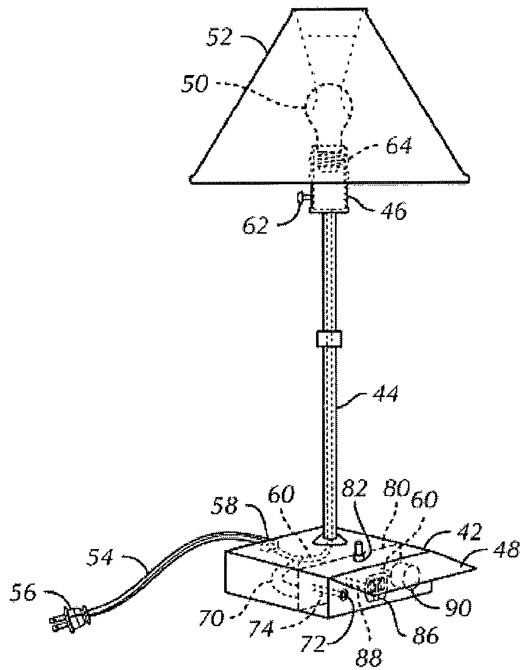
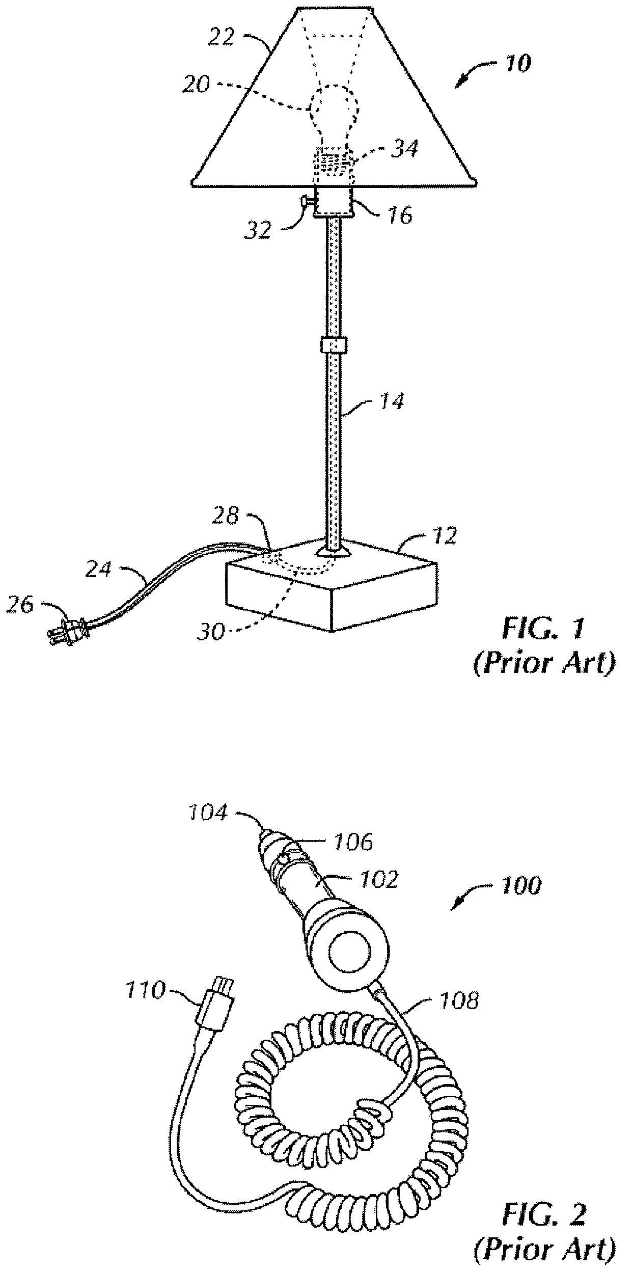
[0031]FIG. 1 shows a prior art table lamp 10. The lamp 10 includes a lamp base 12 by which the lamp 10 is supported from a table, floor or other surface. There is a support 14 such as a pole or pedestal; that supports a light holding fixture 16. The light holding fixture 16 holds an illuminating element 20 such as a bulb 20 (shown in hidden lines). The may be a light diffusing element 22 such as a shade 22 or a frosted lens or th...


PUM


Abstract

A lamp base having an electrical device recharging receptacle configured to receive a plug from a recharging device for a portable rechargeable electronic device. The receptacle is configured as a standard automobile cigarette lighter receptacle. The receptacle includes standard cigarette lighter receptacle electrical contacts that are connected to a voltage and current conversion circuit for receiving standard household voltage and converting it into standard automotive voltage and current. An adapter receptacle is provided in the lamp base with securable replacement electrical and mechanical connection mechanism, wherein the conversion circuit provides a voltage and current to the adapter receptacle. A replaceably securable USB adapter plug comprising a second conversion circuit for converting the voltage and current provided to the adapter receptacle into a standard USB voltage and current. The replaceably securable USB adapter plug may be electrically and mechanically disconnected and replaced with an upgraded replaceably securable USB adapter plug having a third conversion circuit to convert the voltage and current provided to a different USB voltage and current.

Description

RELATED APPLICATIONS[0001]This application is a continuation-in-part of co-pending and co-owned U.S. patent application Ser. No. 11 / 788,424 filed Apr. 20, 2007, that is relied upon for priority and that is incorporated herein by reference for all legitimate purposes.BACKGROUND OF INVENTION[0002]Portable electronic devices have become more and more popular in recent years. For example, portable radios, portable music recording a music playing devices, portable cellular telephones, portable hand held personal data assistants (PDAs) and portable handheld and laptop computers are very popular. Portable electronic devices are typically powered with batteries when used in a portable mode or a plug-in power supply when used in a stationary mode. Many such devices are provided with optional rechargeable batteries or with permanently installed rechargeable batteries. In such cases a plug-in power supply device may either provide operating electrical power or electrical power for recharging t...

Claims


Application Information

Patent Timeline
Patent Type & Authority Patents(United States)
IPC IPC(8): F21S8/08
CPCF21S6/002F21S6/005F21V33/00H01R13/6675H01R25/003H01R33/92H01R13/623
Inventor PATEL, BHARAT
Owner PATEL BHARAT
Learn More