
Apparatus and process for distributing vapor and liquid phases

a technology of liquid phase and apparatus, applied in the direction of combustion air/fuel air treatment, separation process, carburetor air, etc., can solve the problems of difficult to correct the problem by altering the liquid level, the problem is not easily remedied, and the flow is maldistributed

Inactive Publication Date: 2013-08-27
UOP LLC
View PDF26 Cites 9 Cited by
  • Summary
  • Abstract
  • Description
  • Claims
  • Application Information

AI Technical Summary

Benefits of technology

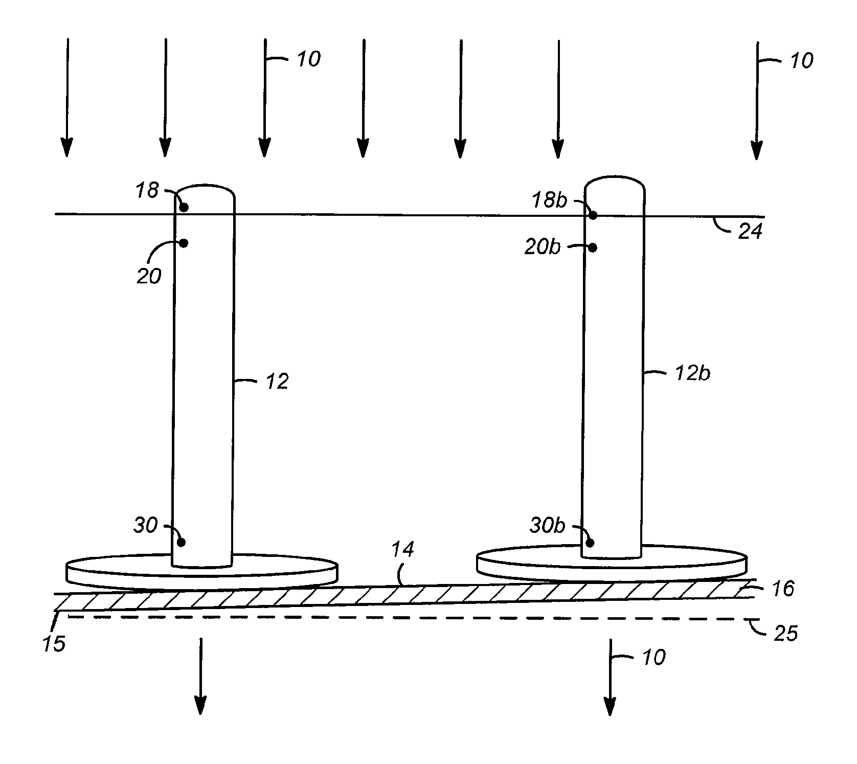
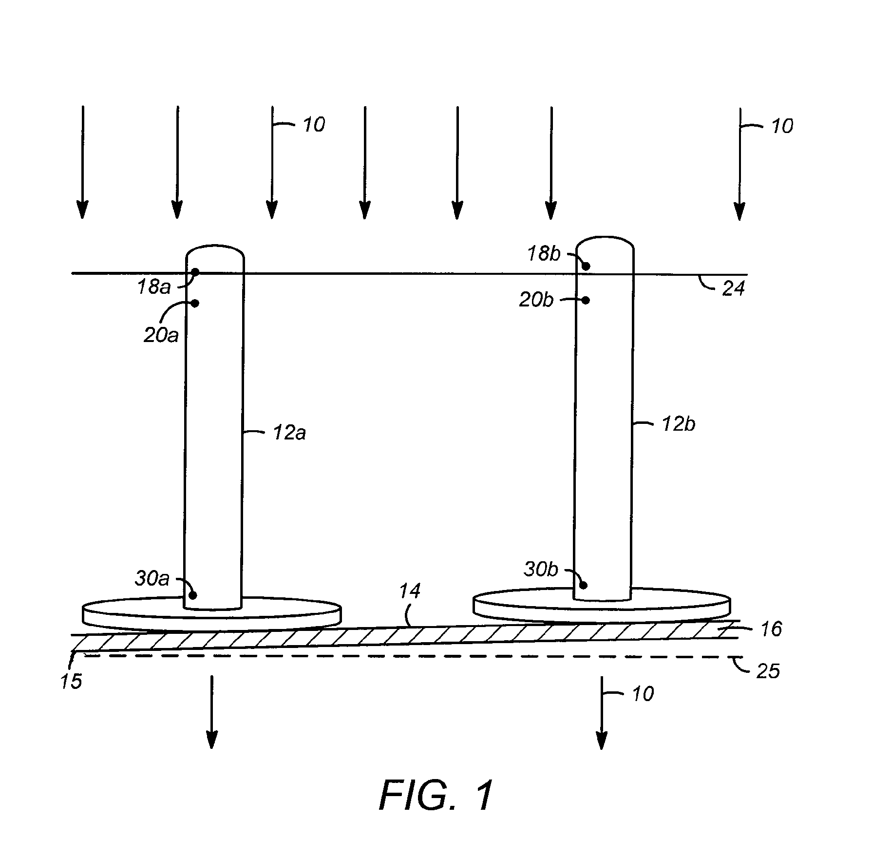
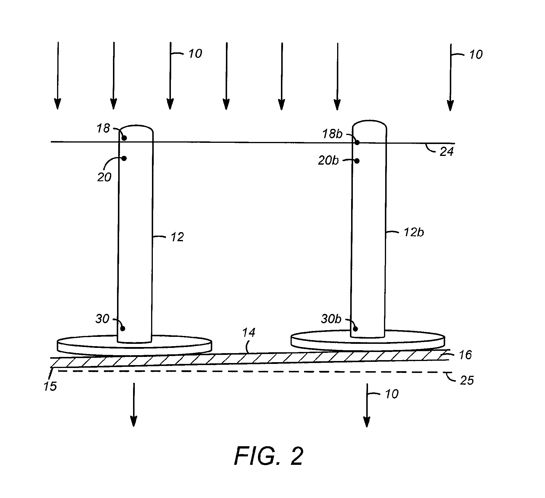
The present invention provides an apparatus and process for controlling the flow of liquids and vapors during a chemical reaction. This is achieved by varying the height of caps and their openings to control the liquid flow profile above a tray. This invention also addresses the issue of non-uniformity in the distribution of liquid across the tray by varying the heights of the highest openings of the caps. This results in a more uniform flow of liquids and vapors and reduces the potential for maldistribution and sudden changes in pressure drop and flow rate.

Problems solved by technology

In view of the fact that large reactor plates generally have an offset in levelness, a large range of liquid flow rates will result in operation with a disproportionate quantity of the equilibrated liquid phase residing at or near the level of openings on one side of the reactor, thereby causing flow maldistribution.
This problem may be observed upon passing vapor and liquid flows through a plurality of elongated caps extending from a distributor tray covering a cross-sectional area of a vapor-liquid contacting apparatus such as a reactor.
The problem is not easily remedied when liquid flow rate is changed, as higher flow rates do not lead to higher liquid levels that would result in covering the openings of caps in an elevated area of the tray.
The problem is difficult to correct by altering the liquid level due to the inherent “inertia” caused by the pressure drop changes discussed above.
Thus, whether or not bottom liquid outlet openings are used, the disproportionate flow of liquid in the depressed area of the tray results in maldistribution of both vapor and liquid flows, to the detriment of the entire process (e.g., hydrotreating or hydrocracking).

Method used


Image

  • Apparatus and process for distributing vapor and liquid phases
  • Apparatus and process for distributing vapor and liquid phases
  • Apparatus and process for distributing vapor and liquid phases

Examples


Embodiment Construction

[0027]The apparatuses and methods for vapor-liquid distribution and contacting are described herein particularly with respect to applications in which uniform distribution of vapor and liquid reactants of a reaction mixture is critical. Such applications include hydroprocessing, which encompasses hydrocracking and hydrotreating processes that are generally very exothermic and require significant attention directed at avoiding “hot spots” and even runaway reactions, which are often associated with flow maldistribution. The apparatuses and methods described herein, however, are broadly applicable to any number of applications involving contacting of a vapor and a liquid, with or without reaction between these phases to form new products. Such applications include refinery and petrochemical production operations including reforming, isomerization, hydrogenation, dehydrogenation, alkylation, cyclization, disproportionation, polymerization, etc. Further applications include those which r...


PUM

PropertyMeasurementUnit
heightaaaaaaaaaa
heightaaaaaaaaaa
heightaaaaaaaaaa

Abstract

Apparatuses and methods are disclosed for distributing vapor and liquid flow. Problems with maldistribution, due to out of level positioning of the distributor tray, are addressed by varying the height of the caps and / or their openings to control the liquid flow profile (distribution) that results due to the rising liquid level.

Description

FIELD OF THE INVENTION[0001]The present invention relates to apparatuses, and processes using the apparatuses, for distributing a vapor and a liquid. In the apparatuses, respective highest or lowest openings (e.g., top and / or side openings) for fluid flow through different elongated caps are at different heights above a tray, from which the caps extend. Fluid maldistribution is thereby reduced or eliminated, for example when the tray is not completely level.DESCRIPTION OF RELATED ART[0002]Devices for distributing vapor and liquid phases are used in a wide range of industrial applications, including petroleum refining and petrochemical production processes. For example, devices for distributing downflowing vapor and liquid phases comprising, respectively, predominantly hydrogen and hydrocarbons, are frequently used in refinery hydroprocessing operations, especially in hydrocracking and hydrotreating reactors.[0003]In many applications involving the flow of vapor and liquid phases, ma...

Claims


Application Information

Patent Timeline
Patent Type & Authority Patents(United States)
IPC IPC(8): B01F3/04
CPCF15D1/001B01D3/205Y10T137/0318B01J4/02B01J10/00C10G45/00C10G47/00
Inventor BANNON, TIMOTHY MICHAEL
Owner UOP LLC
Learn More