
Blast treatment method and blast treatment device

a treatment method and a technology of a treatment device, applied in the direction of weapons, ammunition, weapon components, etc., can solve the problem of inability to adequately destroy the ammunition housed inside the sealed container, and achieve the effect of safe and easy treatmen

Inactive Publication Date: 2013-08-27
KOBE STEEL LTD
View PDF16 Cites 5 Cited by
  • Summary
  • Abstract
  • Description
  • Claims
  • Application Information

AI Technical Summary

Benefits of technology

[0007]Therefore, an object of the present invention is to provide a blast treatment method capable of treating ammunitions housed in a sealed container easily and more safely.
[0009]According to this method, the treatment subject being exposed comparatively easily as a result of the sealed container being divided by the shaped charge in the chamber, the exposed treatment subject is treated while still housed in the chamber by the blast energy of the blasting explosive placed outside the sealed container. This prevents a harmful chemical agent contained in the treatment subject from being dispersed to the outside, and enables the chemical agent to be blast-treated safely and easily.

Problems solved by technology

Thus, in the case of applying this conventional method to, for example, an ammunition in which the explosive is housed in a sealed container that is sturdier than a shell and the like in order to prevent escape of a chemical agent contained in the ammunition, there is the risk of being unable to adequately destroy the ammunition housed inside the sealed container.Patent Document 1: Japanese Patent Application Laid-open No. 2008-309954

Method used


Image

  • Blast treatment method and blast treatment device
  • Blast treatment method and blast treatment device
  • Blast treatment method and blast treatment device

Examples


first embodiment

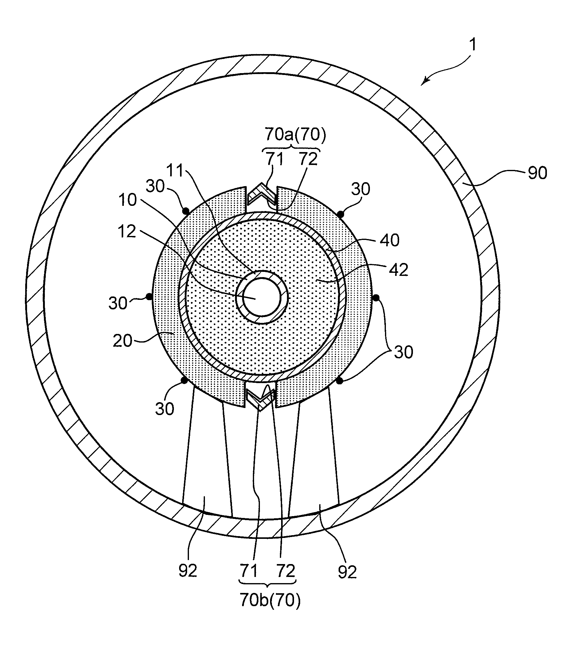
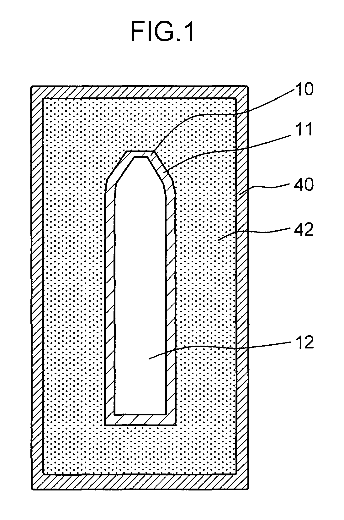
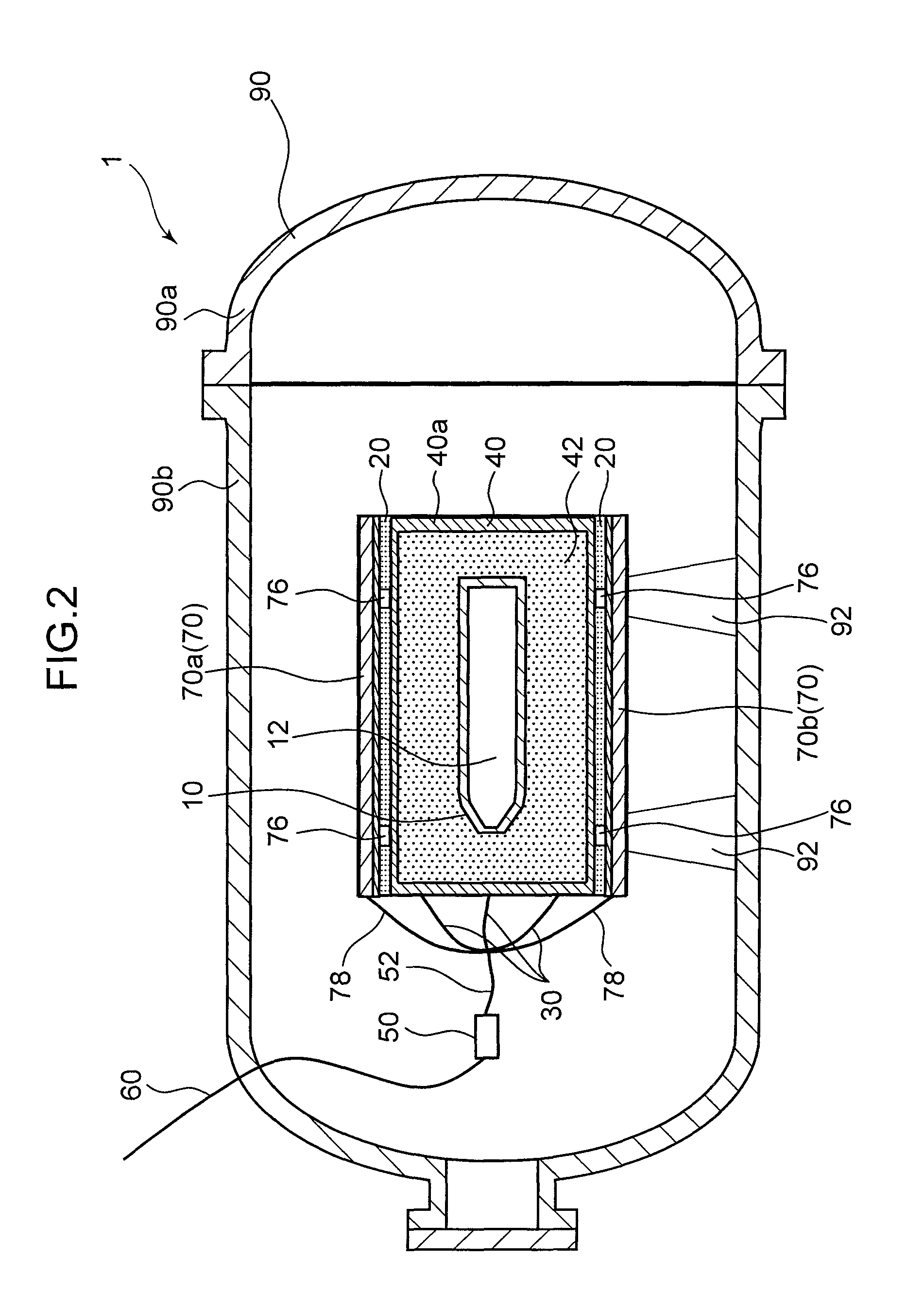
[0022]The following provides an explanation of the blast treatment method according to the present invention with reference to the drawings. FIG. 1 is a cross-sectional view of a state in which a chemical ammunition 10 is housed in a sealed container 40, the chemical ammunition 10 indicated as an example of a subject to be blast-treated by the present blast treatment method. In addition, FIGS. 2 and 3 are each schematic cross-sectional views of a blast treatment device 1 used in the present blast treatment method, while FIG. 4 is a schematic perspective view showing an enlarged view of the inside of the blast treatment device 1.

[0023]The chemical ammunition 10, which is an example of a treatment subject, has an elongated shape in the axial direction as shown in FIG. 1, and is composed of a steel shell (casing) 11 and a harmful substance in the form of a chemical agent 12 housed within this shell. This chemical ammunition 10 is housed in the sealed container 40 while covered with a c...

second embodiment

[0058]The following provides an explanation of the blast treatment method according to the present invention with reference to the drawings.

[0059]FIG. 7 is a cross-sectional view of a blast treatment device 101 used in this second embodiment, while FIG. 8 is a schematic perspective view showing an enlarged view of the inside of the blast treatment device 101. Here, the same reference symbols are used to indicate those constituents of the second embodiment that are the same as those of the first embodiment, and a detailed explanation thereof is omitted. In the present second embodiment, the inner explosive 20 and the cord-like explosive elements 30 of the first embodiment are omitted, and two blasting shaped charges (blasting explosives) 120 to be subsequently described are used to blast the chemical ammunition 10. In addition, two shaped charges 70c and 70d are further placed on the outside of the sealed container 40 in addition to the two shaped charges 70a and 70b arranged in para...

third embodiment

[0073]Next, an explanation is provided of the blast treatment method according to the present invention with reference to the drawings.

[0074]FIG. 11 is a cross-sectional view of a blast treatment device 301 used in this embodiment, while FIG. 12 is a schematic perspective view showing the inside of the blast treatment device 301 after a dividing step to be subsequently described. Here, the same reference symbols are used to indicate those constituents of the third embodiment that are the same as those of the second embodiment, and a detailed explanation thereof is omitted. In the present third embodiment, the blasting shaped charges 120 of the second embodiment are omitted, and the chemical ammunition 10 is blasted using a stationary explosive 320 for the blasting explosive.

[0075]The stationary explosive 320 is an explosive, such as an explosive composed of TNT or an emulsion explosive, that has a rectangular shape that has been formed into the shape of a plate. A length W_320 of on...


PUM


Abstract

Provided is a blast treatment method that enables blast treatment of a treatment subject in a sealed container to be carried out easily and safely. This blast treatment method implements: a shaped charge placement step of placing a shaped charge 70 at a location outside a sealed container 40; a blasting explosive placement step of placing a blasting explosive 20 for blasting a treatment subject 10 at a location outside the sealed container 40; a housing step of housing the sealed container 40 in which the treatment subject 10 is housed in a sealable chamber 90; a dividing step of initiating the shaped charge 70 and dividing the sealed container 40 at prescribed dividing surfaces 40a and 40b with the initiated shaped charge 70 to expose the treatment subject 10; and a blasting step of blast-treating the exposed treatment subject 10 with the blast energy of the blasting explosive 20 by initiating the blasting explosive 20 in the sealed chamber 90.

Description

TECHNICAL FIELD[0001]The present invention relates to a blast treatment method for blast treatment of military and other ammunitions.Background Art[0002]The configuration of military ammunitions (such as artillery shells, bombs, landmines or underwater mines) is known to consist of the providing of a bursting charge and a chemical agent within a steel shell.[0003]Blast treatment is known to be employed for the treatment of these explosives. Since blast treatment does not require disassembly work, it can be applied to not only the treatment of ammunitions that remain well-preserved, but also ammunitions that are difficult to disassemble due to deterioration over time and deformation. In the case of treating ammunitions having chemical agents that are harmful to the human body, the application of this treatment method offers the advantage of being able to completely decompose nearly whole the chemical agents by realizing an ultra-high temperature field and ultra-high pressure field ba...

Claims


Application Information

Patent Timeline
Patent Type & Authority Patents(United States)
IPC IPC(8): F42D5/04
CPCF42B33/06F42D5/045F42D3/00F42D5/04
Inventor KOIDE, KENJIKITAMURA, RYUSUKE
Owner KOBE STEEL LTD
Learn More