
Radiometric heating/sensing probe

a radiometric heating/sensing probe and antenna technology, applied in the field of integrated antenna catheters or probes, can solve the problems of difficult to reliably manufacture at a reasonable cost a thin-wall, difficult to make on a high-volume basis, and fragile sleeves, so as to facilitate the tuning of the impedance of the stub, facilitate the effect of reducing the overall cost of same, and easy and less expensive to mak

Active Publication Date: 2013-08-20
CORAL SAND BEACH LLC
View PDF23 Cites 71 Cited by
  • Summary
  • Abstract
  • Description
  • Claims
  • Application Information

AI Technical Summary

Benefits of technology

[0017]A further object of the invention is provide such a probe which is simpler and less expensive to make than prior comparable probes of this general type.
[0018]Still another object of the invention is to provide a probe of this type which has accurate and reliable operating parameters.
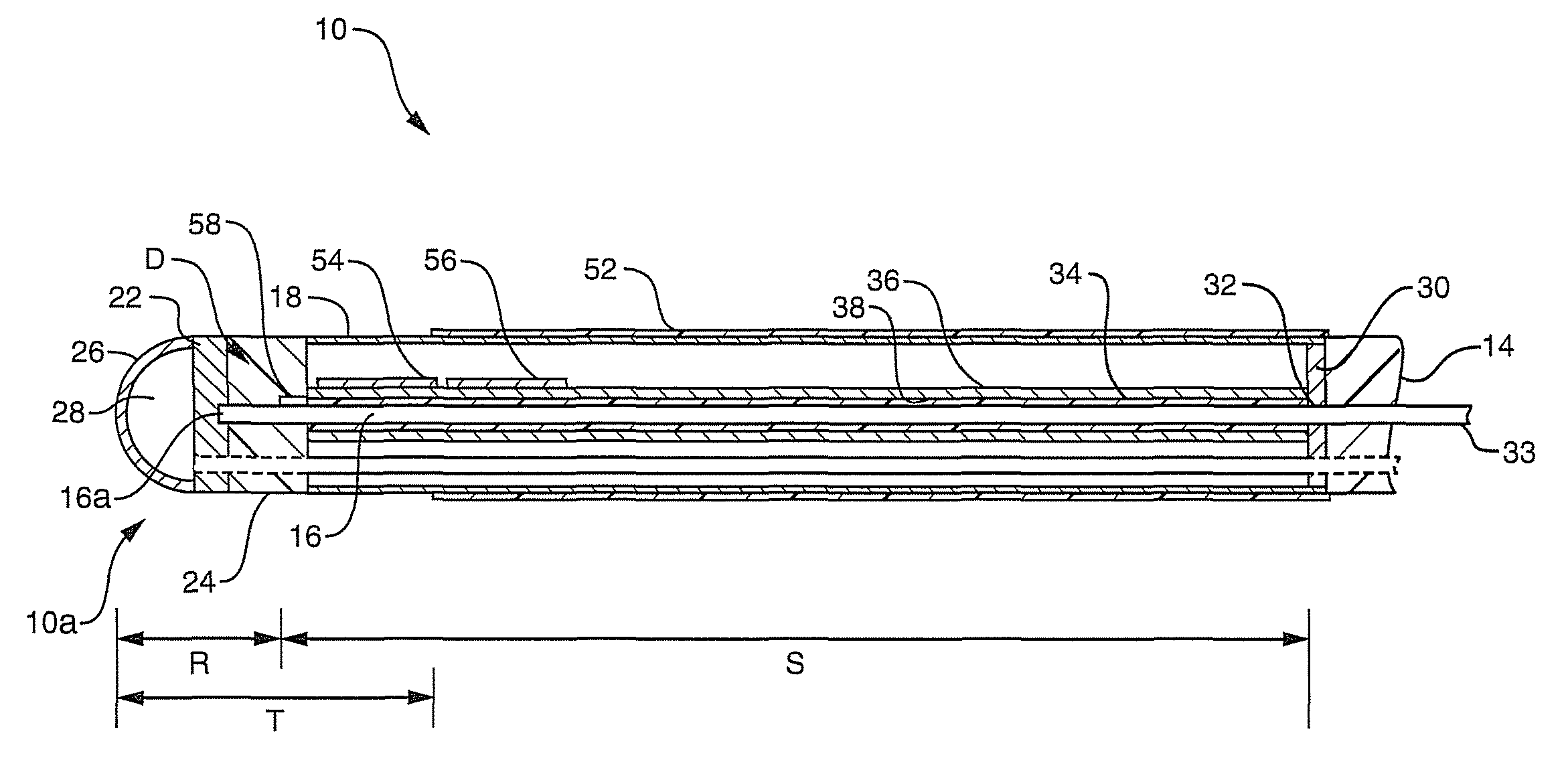
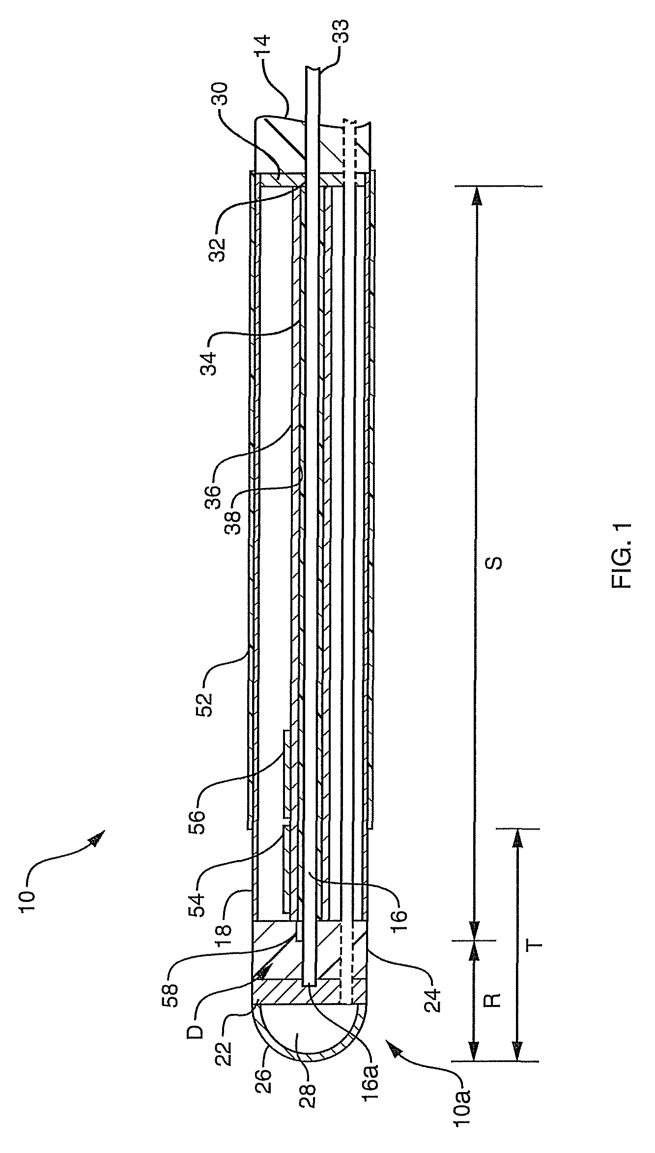
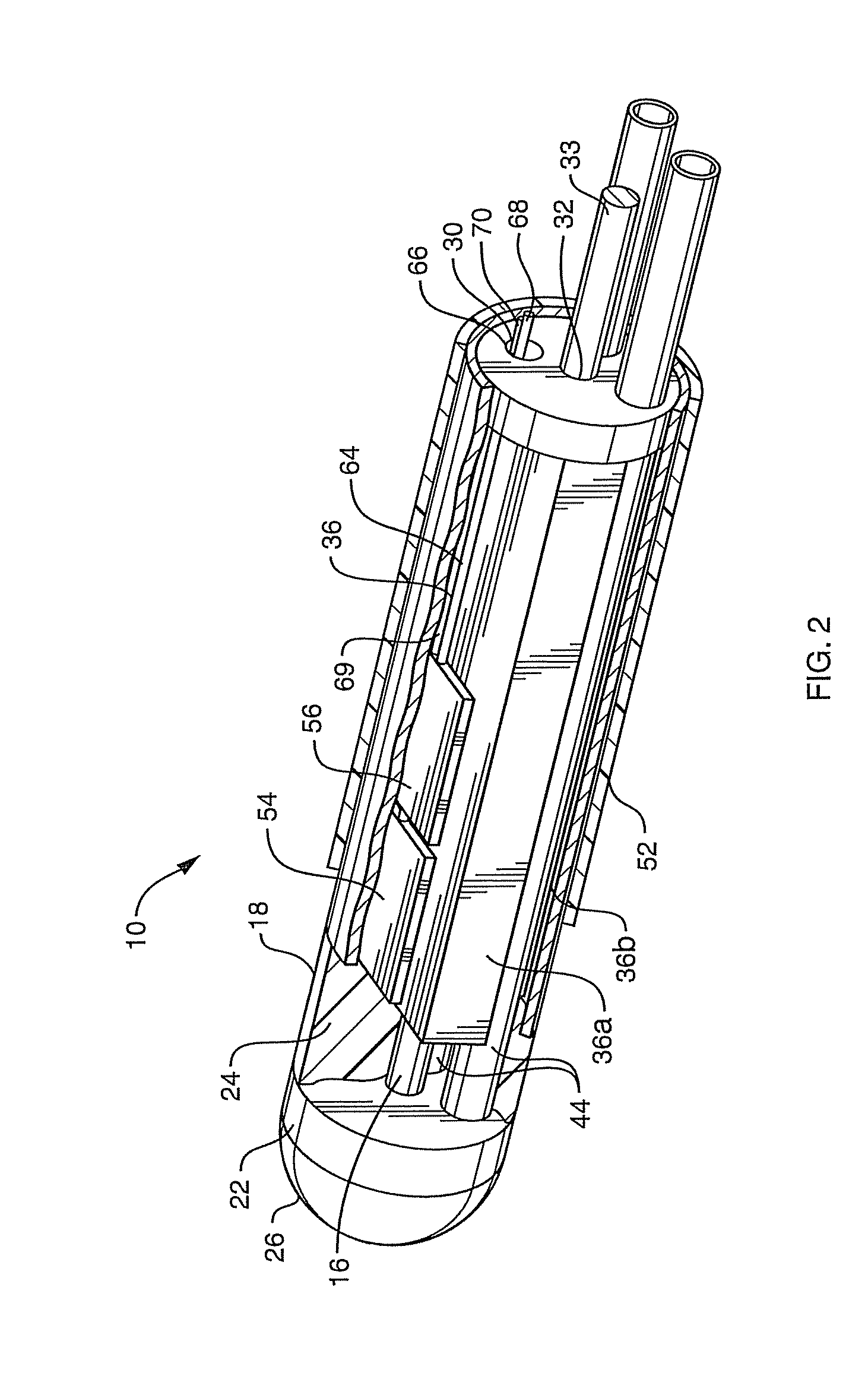
[0023]However, instead of utilizing the center conductor in a coaxial transmission line to form the stub as described in my above application, the stub in the present probe comprises a transmission line of the slab-line or suspended substrate type. This type of transmission line does not require a dielectric sleeve around the center conductor as described in the above prior application. Accordingly, this quarter wave stub is easier and less expensive to make than the prior stub. Consequently, its incorporation into the present probe minimizes the overall cost of same.
[0024]Also, as we shall see, the utilization of a slab-line or suspended substrate-type quarter wave stub in the present probe facilitates tuning the impedance of the stub. It also enables the use in the probe of a relatively large diameter center conductor without materially increasing the overall diameter of the probe. This, in turn, enables the center conductor to be formed as a tube by which a cooling or irrigation fluid may be conducted to, and dispensed from, the probe tip.

Problems solved by technology

In practice, we have found that it is quite difficult to reliably manufacture at a reasonable cost a thin-wall, e.g. 0.005 in, dielectric sleeve 34 of alumina ceramic.
Such sleeves are quite fragile and difficult to make on a high volume basis.

Method used


Image

  • Radiometric heating/sensing probe
  • Radiometric heating/sensing probe
  • Radiometric heating/sensing probe

Examples


Embodiment Construction

[0036]Refer now to FIGS. 4 and 5 of the drawings which show the probe of this invention indicated generally at 100. The former figure illustrates the probe fully assembled, while in the latter figure, the probe is in a disassembled state. As seen there, the probe comprises an inner or center conductor 102 supported by a conductive carrier or is insert 104. Carrier 104 is formed from a cylindrical metal body having an axial passage 106 that receives conductor 102. Upper and lower sectors of that body inboard the ends thereof are milled away to expose passage 106 and conductor 102 therein and to form upper and lower substantially parallel flats 108a and 108b. Flat 108a is composed of coplanar rectangular areas 108aa spaced on opposite sides of conductor 102 near the top thereof. Likewise, flat 108b comprises two coplanar rectangular areas 108bb spaced on opposite sides of conductor 102 near the bottom thereof. Thus, carrier 104 is composed of a center segment 104a containing the flats...


PUM


Abstract

A radiometric heating / sensing probe for radiating electromagnetic waves of a first frequency capable of heating tissue and detecting electromagnetic waves of a second frequency emitted by the tissue indicating tissue temperature. The probe includes a dual frequency antenna, a signal transmitting path to the antenna and a signal receiving path from the antenna to a radiometer. A diplexer connected between those paths inside the probe includes a quarter wave stub in the form of a shorted slab line-type transmission line in the signal transmitting path. The entire probe package is only about 0.4 in. long and 0.08 in. in diameter so that it can be used in many minimally invasive applications.

Description

RELATED APPLICATION[0001]This application is a continuation-in-part of Ser. No. 11 / 474,883, filed Jun. 26, 2006; now U.S. Pat. No. 7,769,469.BACKGROUND OF THE INVENTION[0002]This invention relates to an integrated antenna catheter or probe which relies on electromagnetic radiation to simultaneously controllably heat, and detect the temperature of, fluid or tissue adjacent to the probe. By placing the probe at the region of interest in the body, one can detect, diagnose and treat certain abnormalities associated with tumors, cardiac arrhythmias, benign prosthetic hyperplasia (BPH) and the like. When placed in a patient's vascular system, the catheter or probe can be used to measure temperature or even to raise tissue temperature during heart surgery. It relates especially to an improved probe of the type described in the above application Ser. No. 11 / 474,883, the entire contents of which are hereby incorporated herein by reference.[0003]Referring first to FIGS. 1 to 3 of the drawings...

Claims


Application Information

Patent Timeline
Patent Type & Authority Patents(United States)
IPC IPC(8): A61B18/18
CPCA61B5/01A61N1/403A61B18/1492A61B18/18A61B2017/00039A61B2017/00084A61B2018/00005A61B2018/00023A61B2018/00702A61B2018/00791
Inventor CARR, KENNETH L.
Owner CORAL SAND BEACH LLC
Learn More