
Steam-hydrocarbon reformer improved manifold support and header box system

a steam-hydrocarbon reformer and header box technology, which is applied in the direction of metal hydrides, inorganic chemistry, chemistry apparatus and processes, etc., can solve the problems of failure at multiple locations, and the expansion of the thermal expansion can be so great, so as to reduce the lateral stress on the manifold

Active Publication Date: 2013-08-20
TECH FRANCE SA
View PDF7 Cites 1 Cited by
  • Summary
  • Abstract
  • Description
  • Claims
  • Application Information

AI Technical Summary

Benefits of technology

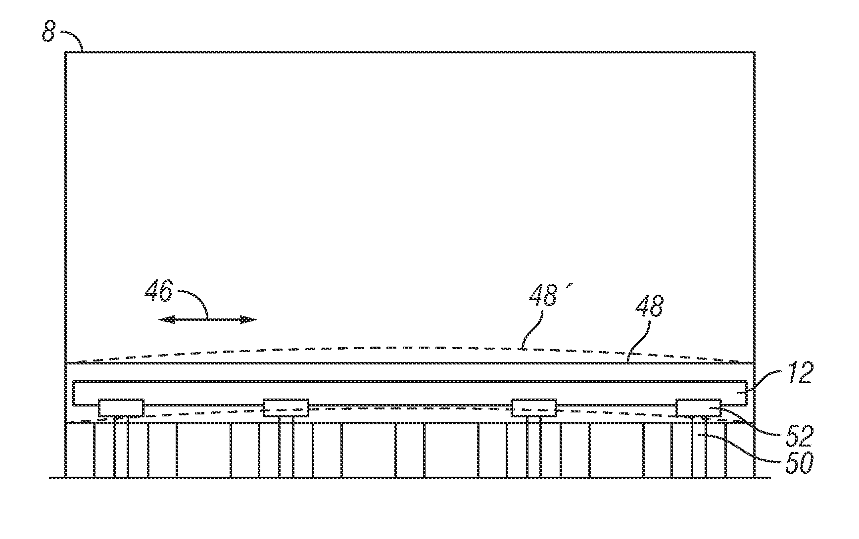
[0017]The disclosure provides an independent support of outlet system in a steam reformer furnace. The thermal expansion of the firebox and / or header box that occurs during operation of a reformer is decoupled from the manifold. The manifold is supported independently on a separate saddle support that supports and allows the manifold to move, while the manifold is still substantially enclosed in the header box. The header box is allowed to expand thermally into different configurations without forcing a substantial change in the manifold configuration. Further, the present invention allows the transfer lines coupled to the manifold through connection tees to laterally move the manifold and reduce lateral stress on the manifold. Thus, the invention provides for independent support of the manifold that allows vertical, lateral, and longitudinal thermal expansion of associated components without overstressing the manifold and causing failures.

Problems solved by technology

However, the thermal expansion can be so great that the above described support system is incapable of sufficient support that still allows the required growth from the thermal expansion during operations.
The expansion can cause twisting and rupture or breakage in one or more of the components and their connections to is adjacent components.
The consequence is failure at multiple locations.
Stresses induced on the various components exceed the allowable stresses and the connections, manifolds, and joints fail.

Method used


Image

  • Steam-hydrocarbon reformer improved manifold support and header box system
  • Steam-hydrocarbon reformer improved manifold support and header box system
  • Steam-hydrocarbon reformer improved manifold support and header box system

Examples


Embodiment Construction

[0028]The Figures described above and the written description of specific structures and functions below are not presented to limit the scope of what Applicants have invented or the scope of the appended claims. Rather, the Figures and written description are provided to teach any person skilled in the art to make and use the inventions for which patent protection is sought. Those skilled in the art will appreciate that not all features of a commercial embodiment of the inventions are described or shown for the sake of clarity and understanding. Persons of skill in this art will also appreciate that the development of an actual commercial embodiment incorporating aspects of the present inventions will require numerous implementation-specific is decisions to achieve the developer's ultimate goal for the commercial embodiment. Such implementation-specific decisions may include, and likely are not limited to, compliance with system-related, business-related, government-related and othe...


PUM


Abstract

The disclosure provides an independent support of outlet system in a steam reformer furnace. The thermal expansion of the firebox and / or header box that occurs during operation of a reformer is decoupled from the manifold. The manifold is supported independently on a separate saddle support that supports and allows the manifold to move, while the manifold is still substantially enclosed in the header box. The header box is allowed to expand thermally into different configurations without forcing a substantial change in the manifold configuration. Further, the present invention allows the transfer lines coupled to the manifold through connection tees to laterally move the manifold and reduce lateral stress on the manifold. Thus, the invention provides for independent support of the manifold that allows vertical, lateral, and longitudinal thermal expansion of associated components without overstressing the manifold and causing failures.

Description

CROSS REFERENCE TO RELATED APPLICATIONS[0001]Not applicable.STATEMENT REGARDING FEDERALLY SPONSORED RESEARCH OR DEVELOPMENT[0002]Not applicable.REFERENCE TO APPENDIX[0003]Not applicable.BACKGROUND OF THE INVENTION[0004]1. Field of the Invention[0005]The invention relates to independent support of an outlet manifold in a steam reformer furnace, and more specifically related to independent support of an outlet manifold within a heated enclosure of a steam reformer furnace.[0006]2. Description of the Related Art[0007]A steam reforming process is a well-established catalytic process that converts natural gas or light hydrocarbons into a mixture containing a major portion of hydrogen. The steam reforming process has gained more and more importance with the increasing demand of various types of gases for the chemical and petrochemical industries, including hydrogen, ammonia, and others. In particular, hydrogen has become a very important product for the refinery desulphurisation and hydro...

Claims


Application Information

Patent Timeline
Patent Type & Authority Patents(United States)
IPC IPC(8): B01J8/00
CPCB01J8/062B01J8/008C01B3/384B01J2219/00024
Inventor PARAMESWAR, SRIKANTIAH N.KAUSHIK, VAIBHAV
Owner TECH FRANCE SA
Learn More