Vehicle battery recharging system and associated method

a battery recharging and vehicle battery technology, applied in battery/fuel cell control arrangement, secondary cell servicing/maintenance, instruments, etc., to prevent overheating and damage to the vehicle battery, prevent battery overvoltage, and prevent overvoltage

Active Publication Date: 2013-08-13
BOSWORTH JUDSON
View PDF10 Cites 13 Cited by
  • Summary
  • Abstract
  • Description
  • Claims
  • Application Information

AI Technical Summary

Benefits of technology

The vehicle electric power generating system described in this patent is a system that uses the air draft generated by the vehicle's movement to generate electrical power and charge the vehicle's battery. It includes an alternator that is connected to the vehicle's battery and a wind driven turbine that is connected to the alternator through a belt. The system automatically regulates the power transfer rate of the alternator and includes sensors to detect power consumption rates of the battery and motor. The system also includes a controller that regulates the power output of the alternator based on the sensor data. The wind driven turbine includes curvilinear blades that maximize the amount of air flow and the system can be integrated into new or existing vehicles. The technical effects of this system include the ability to constantly charge the vehicle's battery while driving, the use of existing infrastructure to avoid the need for costly energy sources, and the ability to regulate the power output of the alternator.

Problems solved by technology

Therefore, a battery or charging system which can retain a vehicle's battery's energy for a longer mileage is one of the issues which the electric car designer has to grapple with.

Method used


Image

  • Vehicle battery recharging system and associated method
  • Vehicle battery recharging system and associated method
  • Vehicle battery recharging system and associated method

Examples


Embodiment Construction

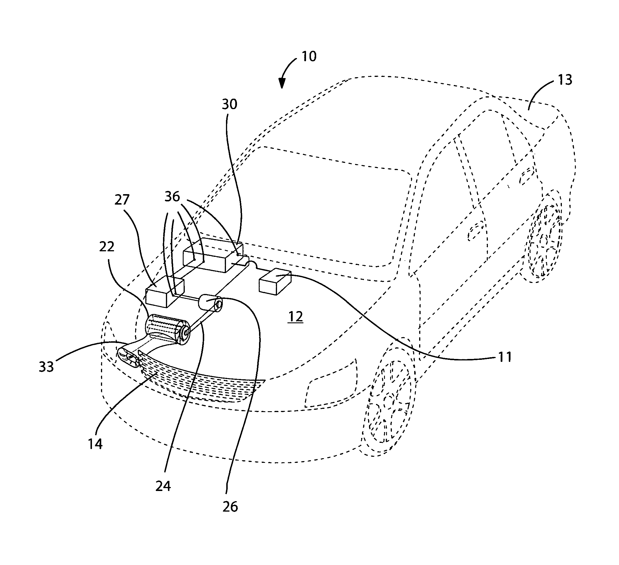
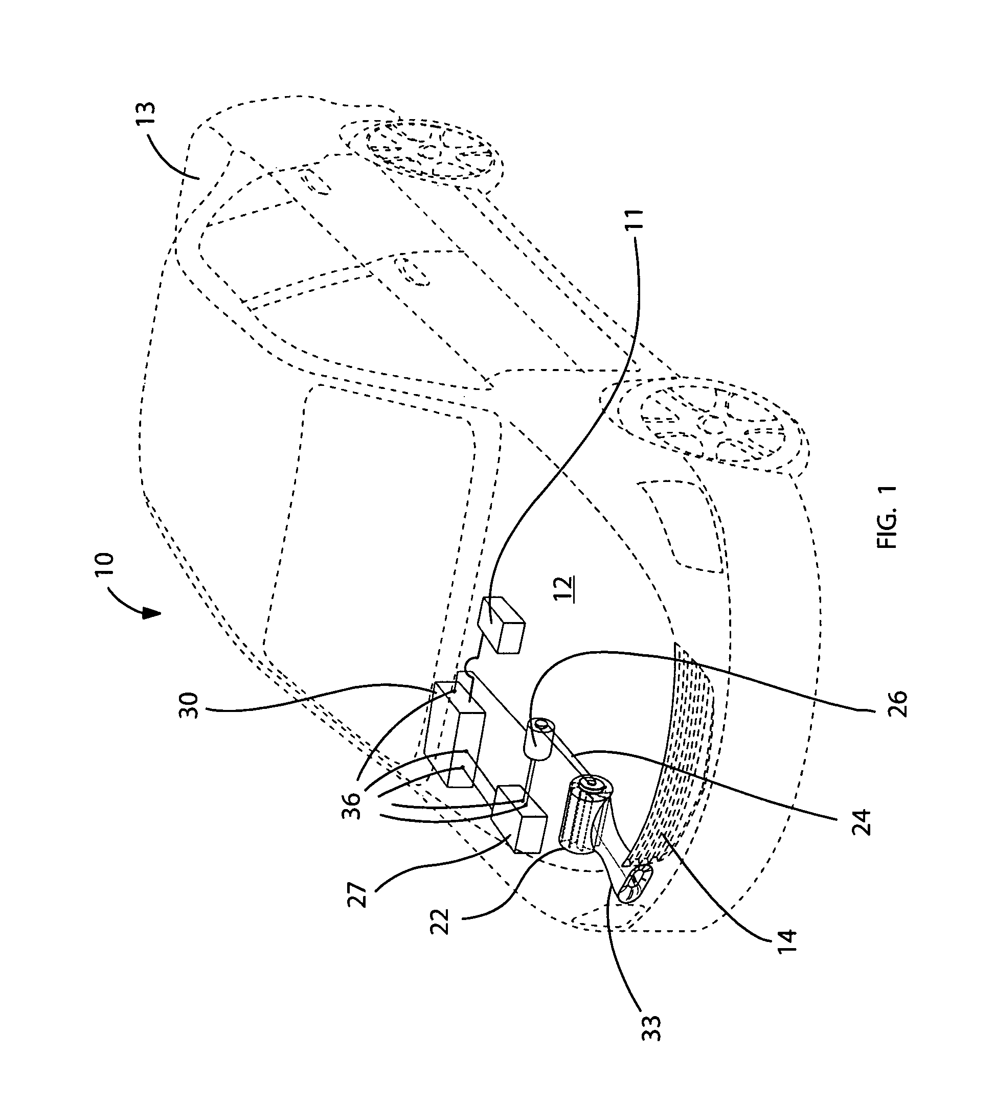
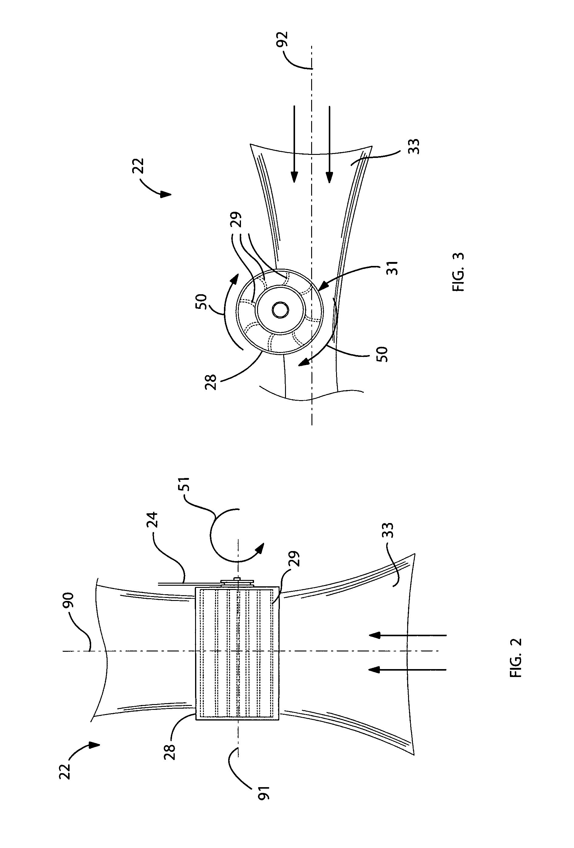
[0034]The present invention will now be described more fully hereinafter with reference to the accompanying drawings, in which a preferred embodiment of the invention is shown. This invention may, however, be embodied in many different forms and should not be construed as limited to the embodiment set forth herein. Rather, this embodiment is provided so that this application will be thorough and complete, and will fully convey the true scope of the invention to those skilled in the art. Like numbers refer to like elements throughout the figures.

[0035]The illustrations of the embodiments described herein are intended to provide a general understanding of the structure of the various embodiments. The illustrations are not intended to serve as a complete description of all of the elements and features of system and systems that utilize the structures or methods described herein. Many other embodiments may be apparent to those of skill in the art upon reviewing the disclosure. Other emb...


PUM


Abstract

A vehicle electric power generating system may include an alternator communicatively coupled to a wind driven turbine and to the existing vehicle battery. A belt may be rotatably coupled to the alternator and the wind driven turbine respectively. A controller may be communicatively coupled to the alternator to automatically regulate the power transfer rate of the alternator. A plurality of sensors may be communicatively coupled to the controller and may be communicatively coupled to the existing vehicle battery as well as an existing vehicle electric motor. First and second switches may be intermediately coupled between the existing vehicle battery and the controller as well as the existing vehicle electrical motor and the controller respectively. Upon synchronous rotation of the wind driven turbine and the belt respectively, the alternator generates an electrical power output adapted to charge the existing vehicle battery.

Description

CROSS REFERENCE TO RELATED APPLICATIONS[0001]This application claims the benefit of U.S. Provisional Application No. 61 / 259,696, filed Nov. 10, 2009, the entire disclosures of which are incorporated herein by reference.STATEMENT REGARDING FEDERALLY SPONSORED RESEARCH OR DEVELOPMENT[0002]Not Applicable.REFERENCE TO A MICROFICHE APPENDIX[0003]Not Applicable.BACKGROUND OF THE INVENTION[0004]1. Technical Field[0005]This invention relates to electric and hybrid vehicles and, more particularly, to a vehicle battery recharging system for providing users with an effective mechanism for recharging a vehicle's battery using wind energy.[0006]2. Prior Art[0007]In 1820, the Danish physicist Hans Christian Oersted discovered that electricity can produce magnetic fields. Oersted's discovery unified the study of electricity and magnetism and resulted in such practical applications as the electromagnet, the telegraph, and the electric motor. In 1831, British physicist Michael Faraday demonstrated t...

Claims


Application Information

Patent Timeline
Patent Type & Authority Patents(United States)
IPC IPC(8): H02J7/32
CPCB60L11/1809H02J7/32B60L3/0046B60L8/006B60L2240/12Y02T90/16B60L58/25Y02T10/70Y02T10/7072
Inventor BOSWORTH, JUDSON
Owner BOSWORTH JUDSON
Why Eureka
Try Eureka