
Sintered ferrite magnet and its production method

a technology of calaco ferrite and ferrite, which is applied in the field can solve the problems of insufficient magnetic properties, insufficient magnetic properties, and inability of calaco ferrite to meet the requirements of high hsub>cj/sub> and high hsub>k, so as to improve the magnetic properties, and improve the effect of sintered ferrite magnets

Active Publication Date: 2013-08-13
HITACHI METALS LTD
View PDF23 Cites 3 Cited by
  • Summary
  • Abstract
  • Description
  • Claims
  • Application Information

AI Technical Summary

Benefits of technology

[0019]It is generally expected that when a material having high magnetic properties is mixed with a material having low magnetic properties in an increasing proportion, the resultant mixture has decreasing magnetic properties. Accordingly, it is expected that sintered magnets obtained by mixing calcined CaLaCo ferrite having high magnetic properties with calcined SrLaCo ferrite having low magnetic properties provides magnetic properties lowering as the mixing ratio of the calcined SrLaCo ferrite increases.
[0020]In an attempt of improving the magnetic properties of sintered CaLaCo ferrite magnets, the inventors have found that sintered magnets obtained by mixing calcined CaLaCo ferrite with calcined SrLaCo ferrite at a particular mass ratio have improved HcJ with little reduction of Br and Hk / HcJ, which are unexpected magnetic properties.

Problems solved by technology

However, their magnetic properties are on the same level as those of conventional Ba ferrites, not sufficiently high.
However, the CaLaCo ferrite of Japanese Patent 3,181,559 has Br and HcJ on the same level as those of SrLaCo ferrites and extremely poor rectangularity Hk / HcJ (hereinafter simply referred to as “Hk / HcJ”), though they have higher HA than that of SrLaCo ferrites.
Thus, the CaLaCo ferrite fails to satisfy both requirements of high HcJ and high Hk / HcJ, being not used in various applications such as motors, etc.

Method used


Image

  • Sintered ferrite magnet and its production method
  • Sintered ferrite magnet and its production method
  • Sintered ferrite magnet and its production method

Examples


example 1

Preparation of Calcined CaLaCo Ferrite

[0213]CaCO3 powder, La(OH)3 powder, Fe2O3 powder and Co3O4 powder were mixed to have a composition represented by Ca1-x′-c′Lax′Ac′Fe2n′-y′Coy′, wherein x′=0.5, c′=0, y′=0.3 and n′=5.2, and 100% by mass of the resultant mixed powder was mixed with 0.1% by mass of H3BO3 to obtain a mixed starting material powder. With water added, this mixed starting material powder was wet-ball-milled for 4 hours, dried, granulated, and calcined at 1250° C. for 3 hours in the air. The resultant calcined body was coarsely pulverized by a hummer mill to prepare coarse powder of calcined CaLaCo ferrite.

[0214]Preparation of Calcined SrLaCo Ferrite

[0215]SrCO3 powder, La(OH)3 powder, Fe2O3 powder and Co3O4 powder were mixed to have a composition represented by Sr1-x″Lax″Fe2n″-y″Coy″, wherein x″=0.2, y″=0.2, and n″=5.8, and 100% by mass of the resultant mixed powder was mixed with 0.1% by mass of H3BO3 to obtain a mixed starting material powder. With water added, this m...

example 2

Preparation of Calcined CaLaCo Ferrite

[0239]CaCO3 powder, La(OH)3 powder, Fe2O3 powder and Co3O4 powder were mixed to have compositions represented by Ca1-x′-c′Lax′Ac′Fe2n′-y′Coy′ (c′=0), wherein 1-x′-c′, x′, y′ and n′ were numbers shown in Table 1-1. 100% by mass of each resultant mixed powder was mixed with 0.1% by mass of H3BO3 to obtain a mixed starting material powder. With water added, each mixed starting material powder was wet-ball-milled for 4 hours, dried, granulated, and calcined at 1250° C. for 3 hours in the air. Each calcined body was coarsely pulverized by a hummer mill to prepare coarse powder of calcined CaLaCo ferrite having each composition of C-1 to C-5.

[0240]

TABLE 1-1Composition of Calcined CaLaCo FerriteCalcinedCa1-x′-c′Lax′Ac′Fe2n′-y′Coy′Body1-x′-c′x′c′y′n′C-10.500.5000.305.20C-20.490.5100.355.30C-30.400.6000.405.30C-40.500.5000.255.20C-50.500.5000.2755.20C-60.450.500.05(1)0.305.30C-70.450.500.05(2)0.305.30Note:(1)Ba was used as the element A.(2)Sr was used as...

example 3

Preparation of Calcined CaLaCo Ferrite

[0288]CaCO3 powder, La(OH)3 powder, BaCO3 powder, Fe2O3 powder and Co3O4 powder were mixed to have a calcined body composition represented by Ca1-x′-c′Lax′Ac′Fe2n′-y′Coy′, wherein A was Ba, and 1-x′-c′, x′, c′, y′ and n′ were shown in No. C-6 in Table 1-1, and 100% by mass of the resultant mixed powder was mixed with 0.1% by mass of H3BO3 to obtain a mixed starting material powder. With water added, this mixed starting material powder was wet-ball-milled for 4 hours, dried, granulated, and then calcined at 1300° C. for 3 hours in the air. The resultant calcined body was coarsely pulverized by a hummer mill to prepare coarse powder of calcined CaLaCo ferrite (Calcined Body C-6).

[0289]Preparation of Calcined SrLaCo Ferrite

[0290]SrCO3 powder, La(OH)3 powder, Fe2O3 powder and Co3O4 powder were mixed to have a calcined body composition represented by Sr1-x″Lax″Fe2n″-y″Coy″, wherein 1-x″, x″, y″ and n″ were shown in No. S-11 in Table 1-2, and 100% by ...


PUM

PropertyMeasurementUnit
Curie temperatureaaaaaaaaaa

Abstract

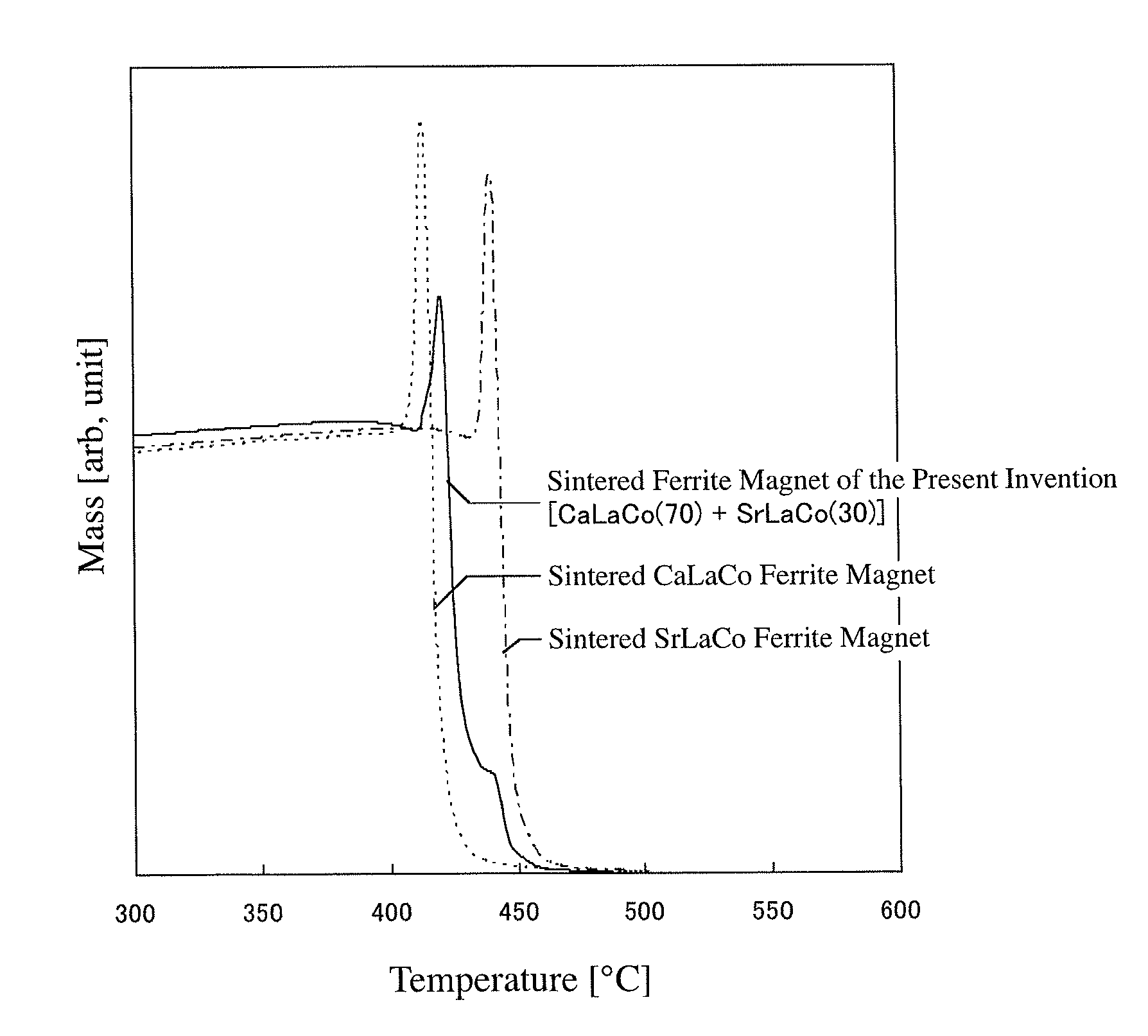
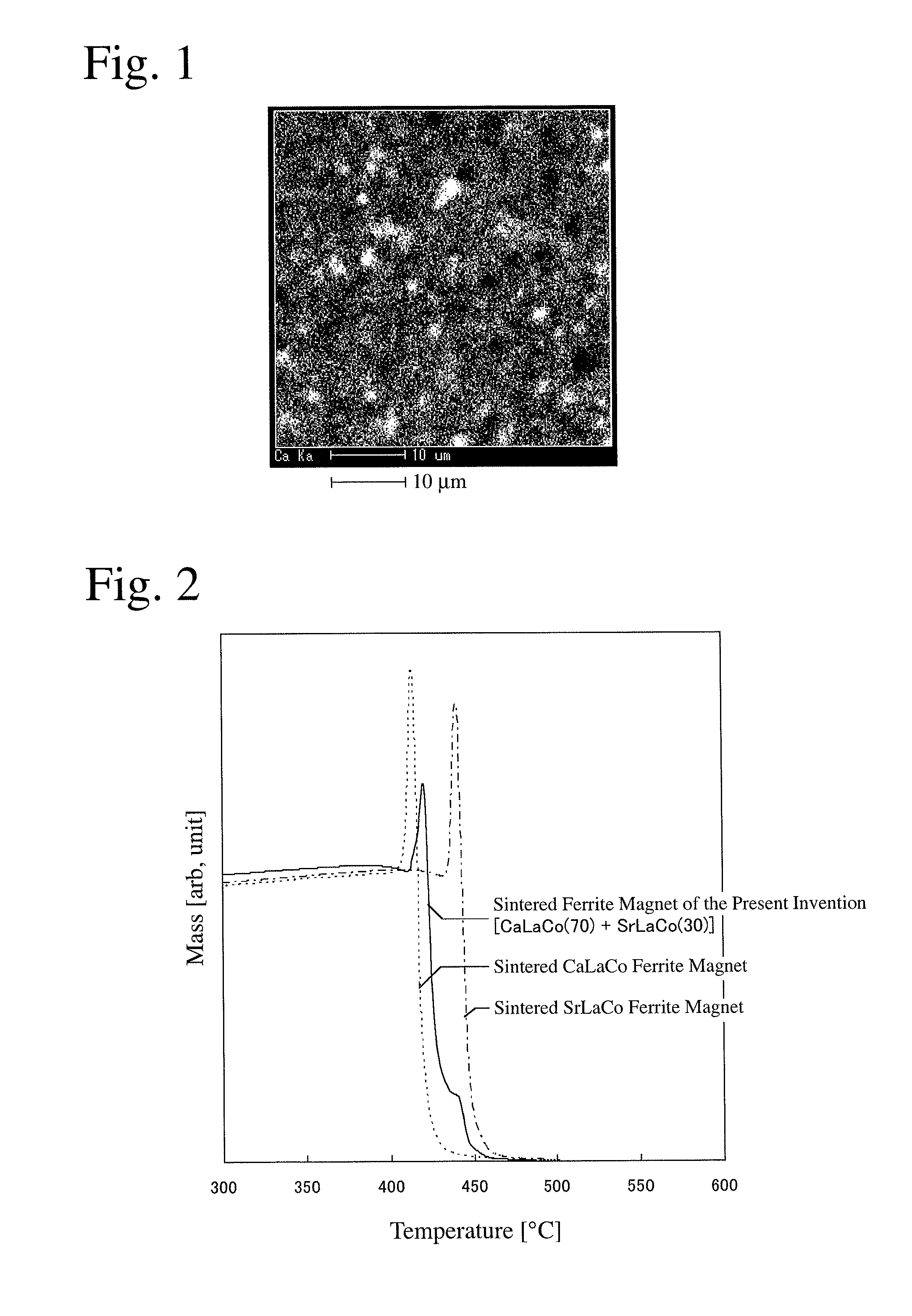
A sintered ferrite magnet comprising a first granular ferrite compound phase containing Ca, La, Fe and Co and having a Curie temperature Tc1 between 415° C. and 430° C., and a second granular ferrite compound phase containing Sr, La, Fe and Co and having a Curie temperature Tc2 between 437° C. and 455° C., the volume ratio of the first ferrite compound phase being 50-90%, and the volume ratio of the second ferrite compound phase being 10-50%, with their total volume ratio being 95% or more.

Description

CROSS REFERENCE TO RELATED APPLICATIONS[0001]This application is a National Stage of International Application No. PCT / JP2011 / 055553, filed on Mar. 9, 2011, which claims priority from Japanese Patent Application No. 2010-053611, filed on Mar. 10, 2010, the contents of all of which are incorporated herein by reference in their entirety.FIELD OF THE INVENTION[0002]The present invention relates to a sintered ferrite magnet having high magnetic properties, and its production method.BACKGROUND OF THE INVENTION[0003]Sintered ferrite magnets are used for various applications such as various motors, electric power generators, speakers, etc. As typical sintered ferrite magnets, Sr ferrite (SrFe12O19) and Ba ferrite (BaFe12O19) having hexagonal, M-type magnetoplumbite structures are known. These sintered ferrite magnets are produced by a powder metallurgy method from starting materials, for example, comprising iron oxide and carbonates of strontium (Sr) or barium (Ba), etc., at relatively low...

Claims


Application Information

Patent Timeline
Patent Type & Authority Patents(United States)
IPC IPC(8): H01F1/11C01G49/00C04B35/40H01F41/02
CPCC01G51/68C04B35/2633C04B35/2641C04B35/6262H01F1/11H01F41/0266C04B35/6268C04B35/62685C04B2235/85C01P2004/04C01P2006/42C04B2235/3208C04B2235/3213C04B2235/3215C04B2235/3217C04B2235/3227C04B2235/3241C04B2235/3272C04B2235/3274C04B2235/3277C04B2235/3418C04B2235/5445C04B2235/605C04B2235/6567C04B2235/6585C04B2235/767C04B2235/785C04B2235/786C04B2235/80C04B2235/3409C04B2235/6584C04B2235/787C01P2002/85C01G49/00C04B35/26H01F41/02
Inventor HOSOKAWA, SEIICHIODA, ETSUSHIIWASAKI, HIROSHI
Owner HITACHI METALS LTD
Learn More