
Trocar system with laparoscope gas channel

a gas channel and trocar technology, applied in the field of first-entry surgical access system, can solve the problems of increasing the risk of damaging the internal organs directly beneath the entry point, and achieve the effect of improving the optical characteristics of the trocar system, precise and accurate visual placemen

Active Publication Date: 2013-08-13
APPL MEDICAL RESOURCES CORP
View PDF160 Cites 12 Cited by
  • Summary
  • Abstract
  • Description
  • Claims
  • Application Information

AI Technical Summary

Benefits of technology

The patent text describes a surgical access system that includes a trocar, an insufflating optical obturator, and a laparoscope. The obturator has a transparent tip with at least one vent hole that is connected to a gas flow channel via the interior surface of the obturator and the laparoscope. This system allows for precise and accurate visual placement into a body cavity, making it suitable as a first entry surgical access system. It is also useful for drug delivery, fluid and tissue aspiration, and allows for bladeless separation of body tissue fibers. Overall, this system provides improved optical characteristics and facilitates safe and effective surgical procedures.

Problems solved by technology

Consequently, inserting the first trocar, referred to as first entry, carries an increased risk of damaging the internal organs directly beneath the entry point.

Method used


Image

  • Trocar system with laparoscope gas channel
  • Trocar system with laparoscope gas channel
  • Trocar system with laparoscope gas channel

Examples


example 1

[0046]A polycarbonate insufflating obturator was manufactured in which the inner diameter of the 5-mm insufflating obturator shaft was 0.235″ (6 mm), the outer diameter was 0.272″ (6.9 mm), and the wall thickness was 0.018″ (0.46 mm). The inner diameter of the mating 5-mm cannula was 0.277″ (7 mm), the outer diameter was 0.343″ (8.7 mm), and the wall thickness of the cannula was 0.033″ (0.84 mm). Based on these dimensions, the cross-sectional area of the obturator flow channel with a 5.5 mm laparoscope inserted therein was 0.0064 in2 (4.1 mm2), which provides a carbon dioxide flow rate of about 6 L / min at an insufflator pressure setting of about 1.6-2 KPa (about 12-15 Torr).

example 3

[0048]A 5-mm obturator is molded from polycarbonate with an inside diameter of 0.230″ (5.8 mm) and a wall thickness of 0.021″ (0.53 mm). The carbon dioxide flow rate through this obturator with a 5.5-mm laparoscope inserted therein is about 3.5 L / minute at an insufflator pressure setting of about 1.6-2 KPa (about 12-15 Torr). The increased wall thickness improves the injection molding process for manufacturing the obturator shaft.

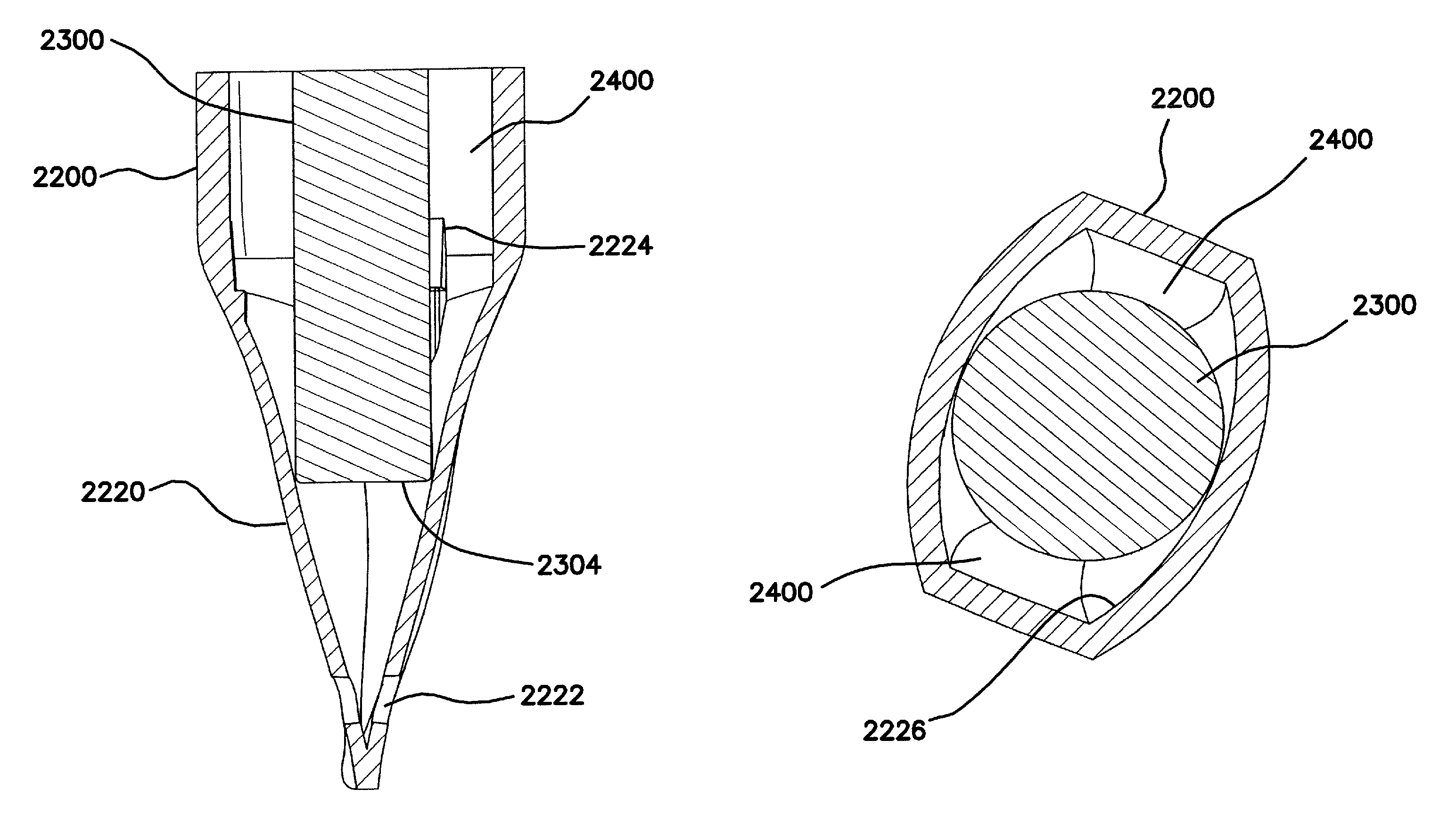
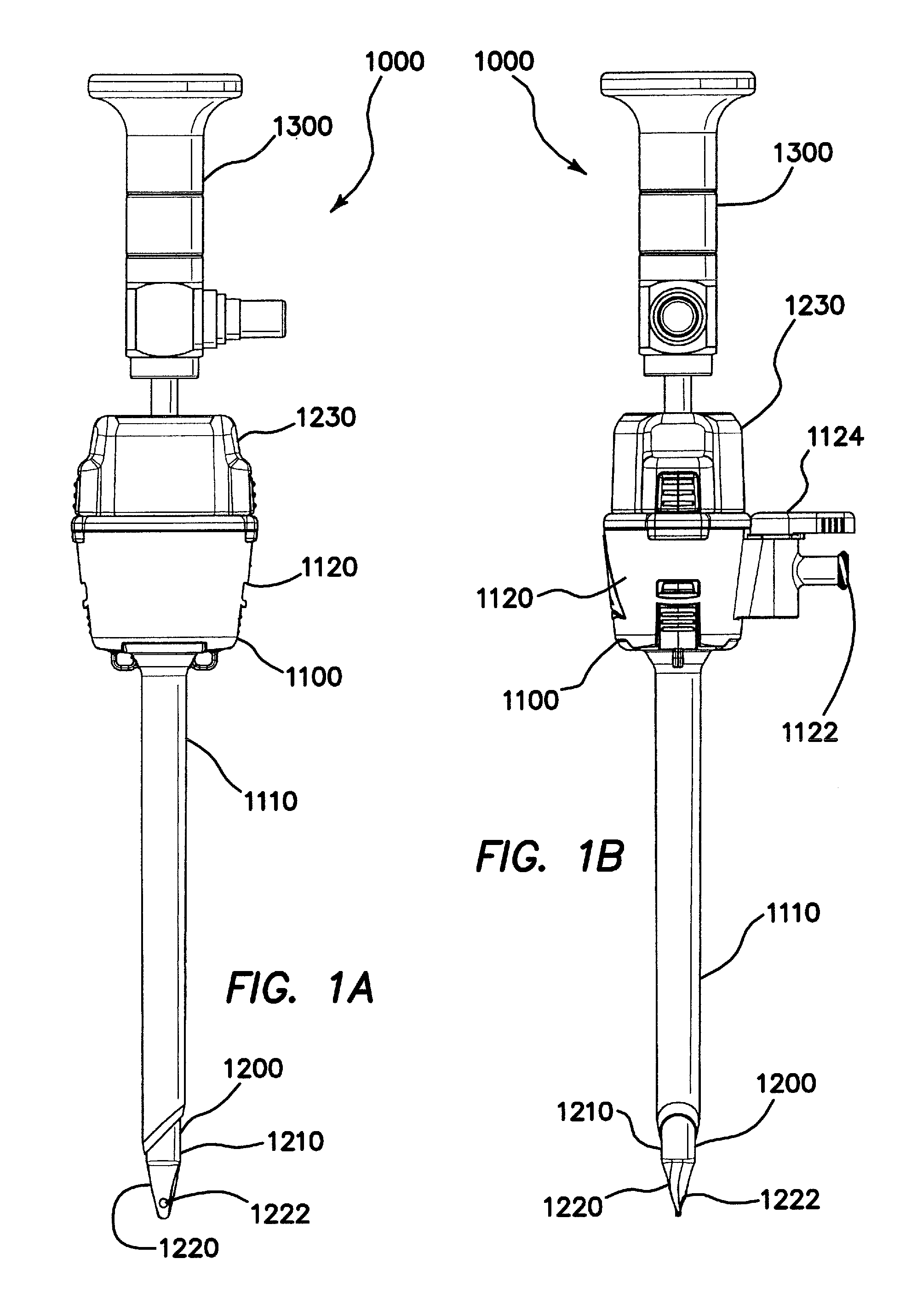
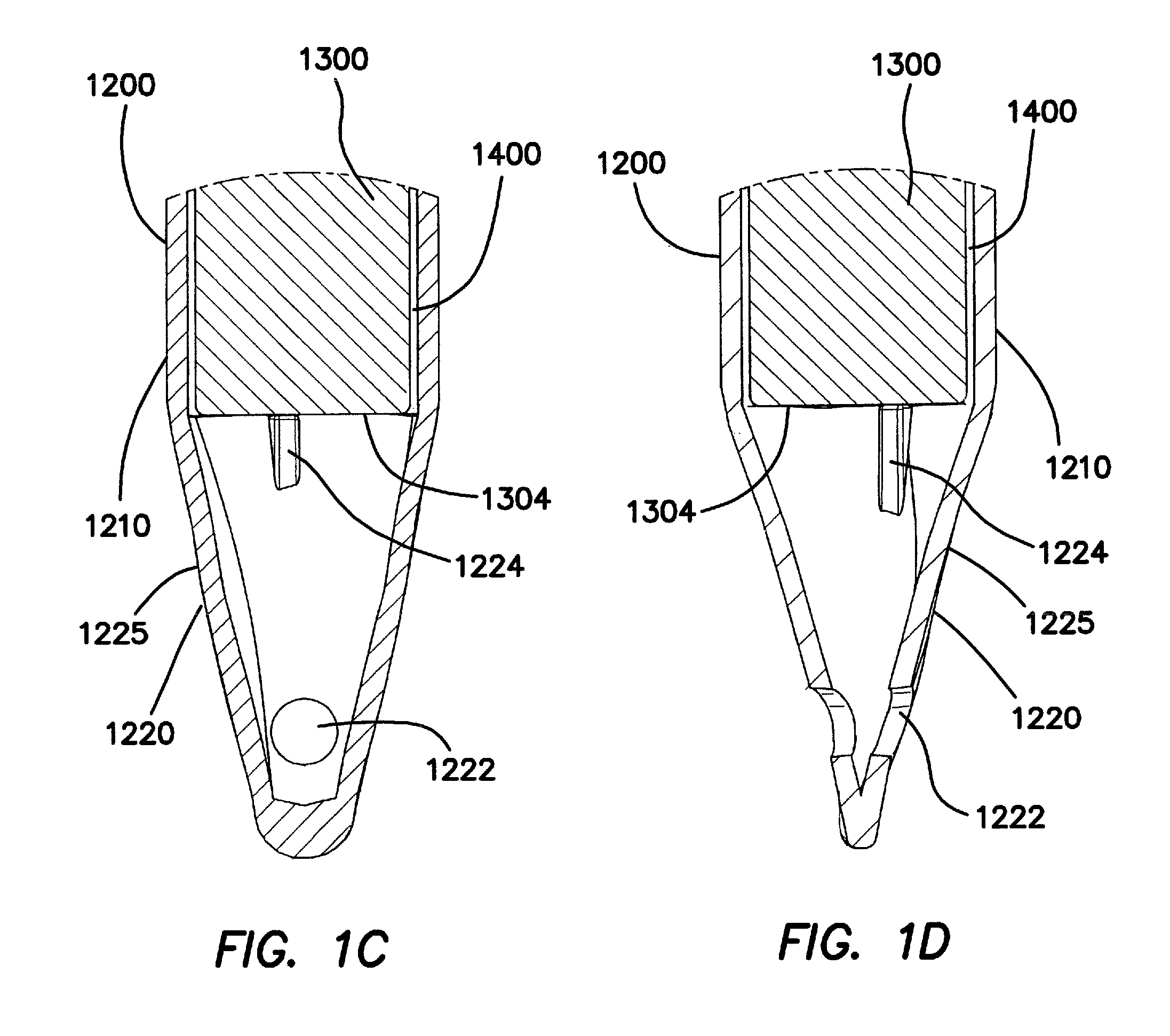
[0049]The tip 1220 of a bladeless insufflating obturator is designed to separate and dilate tissue and muscle fibers during traversal of a body wall. Because of the dilating and separating properties of a 5-mm insufflating trocar, increasing the outer diameters of the obturator shaft 1210 and the cannula 1110, as compared with typically sized 5-mm bladeless trocars, does not adversely affect the insertion force of the trocar in the illustrated embodiment. The wall thickness of the obturator shaft 1210 is also sufficient to permit injection molding the shaft...


PUM


Abstract

A surgical access system comprises a trocar, an insufflating optical obturator slidably insertable into the trocar, and a laparoscope slidably insertable into the obturator. A distal end of the obturator comprises a tip, at least a portion of which comprises a wall with a generally uniform thickness comprising a transparent material. At least one vent hole disposed at the obturator tip is fluidly connected to a gas flow channel defined by an interior surface of the obturator and the laparoscope, which is fluidly connected to an insufflation gas inlet disposed at a proximal end of the trocar. Improved optical characteristics of the trocar system permit precise and accurate visual placement thereof into a body cavity. Accordingly the access system is suitable as a first entry surgical access system. Embodiments of the trocar access are also useful for drug delivery, and / or for fluid and / or tissue aspiration.

Description

CROSS REFERENCE TO RELATED APPLICATION[0001]This application claims the benefit of U.S. Application No. 61 / 101,061, filed Sep. 29, 2008, the entire disclosure of which is incorporated by reference.BACKGROUND[0002]1. Technical Field[0003]This disclosure is generally directed to surgical access devices, and more particularly, to a first-entry surgical access system.[0004]2. Description of the Related Art[0005]Trocars are used for instrument access to body cavities in minimally invasive surgery, for example, laparoscopic surgery. In laparoscopic surgery of the organs of the abdomen, the abdomen is typically inflated or insufflated with an insufflation gas, for example, carbon dioxide, which lifts the abdominal wall away from the internal organs, thereby facilitating access to the organs, a condition referred to as pneumoperitoneum. Inserting trocars into an abdomen under pneumoperitoneum is relatively easy. Because the abdominal wall is distended away from the internal organs by the pr...

Claims


Application Information

Patent Timeline
Patent Type & Authority Patents(United States)
IPC IPC(8): A61M37/00
CPCA61B17/3417A61B17/3474A61B1/3132A61B1/313A61B19/52A61B2017/00902A61B2017/00907A61B2017/3454A61B19/5212A61B90/36A61B90/361A61B17/00234A61B1/00154A61B17/0218A61B17/3423A61B17/3496A61B2017/3419
Inventor KAHLE, HENRYSTROKOSZ, ARKADIUSZTAYLOR, SCOTT V.
Owner APPL MEDICAL RESOURCES CORP
Learn More