De-noising method for multi-microphone audio equipment, in particular for a "hands free" telephony system

a multi-microphone audio and de-noise technology, applied in the field of speech processing, can solve problems such as difficulty in estimating useful parameters for processing

Active Publication Date: 2013-08-06
PARROT
View PDF13 Cites 6 Cited by
  • Summary
  • Abstract
  • Description
  • Claims
  • Application Information

AI Technical Summary

Benefits of technology

[0010]Most techniques are based on the assumption that the useful signal and / or the interfering noise presents a certain amount of directivity, and they combine the signals from the various microphones so as to improve the signal / noise ratio as a function of such directivity conditions.
[0011]Thus, EP 2 293 594 A1 (Parrot SA) describes a method of spatial detection and filtering of noise that is not steady and that is directional, such as a sounding horn, a passing scooter, an overtaking car, etc. The technique proposed consists in associating spatial directivity with the non-steady time and frequency properties so as to detect a type of noise that is usually difficult to distinguish from speech, and thus provide effective filtering of that noise and also deduce a probability that speech is present, thereby enabling noise attenuation to be further improved.
[0020]selectively reducing noise in this single channel, for each bin, as a function of the probability that speech is present.
[0027]e) on the basis of the probability of speech being present and of the combined signal given by the projector calculated in step d), selectively reducing the noise by applying variable gain specific to each frequency band and to each time frame.

Problems solved by technology

The main difficulty associated with the methods of speech processing by multi-channel systems is the difficulty of estimating useful parameters for performing the processing, since the estimators are strongly linked with the surrounding environment.

Method used


Image

  • De-noising method for multi-microphone audio equipment, in particular for a "hands free" telephony system
  • De-noising method for multi-microphone audio equipment, in particular for a "hands free" telephony system
  • De-noising method for multi-microphone audio equipment, in particular for a "hands free" telephony system

Examples


Embodiment Construction

[0047]There follows a detailed description of the de-noising technique proposed by the invention.

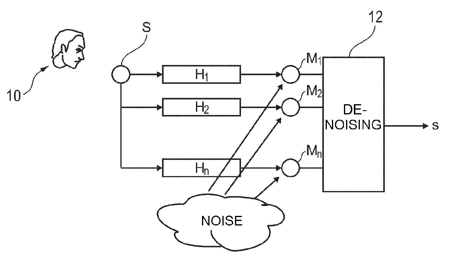
[0048]As shown in FIG. 1, consideration is given to a set of n microphone sensors, it being possible for each sensor to be considered as a single microphone M1, . . . , Mn picking up a reverberated version of a speech signal uttered by a useful signal source S (the speech from a near speaker 10), which signal has noise added thereto.

[0049]Each microphone thus picks up:[0050]a component of the useful signal (the speech signal);[0051]a component of the reverberation of this speech signal as produced by the vehicle cabin; and[0052]a component of the surrounding interfering noise in all of its forms (directional or diffuse, steady or varying in unpredictable manner, etc.).

Modeling the Signals as Picked Up

[0053]The (multiple) signals from these microphones are to be processed by performing de-noising (block 12) so as to give a (single) signal as output: this is a single input multiple output ...


PUM


Abstract

This method comprises the following steps in the frequency domain:a) estimating a probability that speech is present;b) estimating a spectral covariance matrix of the noise picked up by the sensors, this estimation being modulated by the probability that speech is present;c) estimating the transfer functions of the acoustic channels between the source of speech and at least some of the sensors relative to a reference constituted by the signal picked up by one of the sensors, this estimation being modulated by the probability that speech is present;d) calculating an optimal linear projector giving a single combined signal from the signals picked up by at least some of the sensors, from the spectral covariance matrix, and from the estimated transfer functions; ande) on the basis of the probability that speech is present and of the combined signal output from the projector, selectively reducing the noise by applying variable gain.

Description

FIELD OF THE INVENTION[0001]The invention relates to processing speech in a noisy environment.[0002]The invention relates particularly, but in non-limiting manner, to processing speech signals picked up by telephony devices for use in motor vehicles.BACKGROUND OF THE INVENTION[0003]Such appliances comprise one or more microphones that are sensitive not only to the voice of the user, but that also pick up the surrounding noise together with the echoes due to the phenomenon of reverberation in the surroundings, typically the cabin of the vehicle. The useful component (i.e. the speech signal from the near speaker) is thus buried in an interfering noise component (external noise and reverberation) that can often make the speech of the near speaker incomprehensible for the remote speaker (i.e. the speaker at the other end of the channel over which the telephone signal is transmitted).[0004]The same applies if it is desired to implement voice recognition techniques, since it is very diffi...

Claims


Application Information

Patent Timeline
Patent Type & Authority Patents(United States)
IPC IPC(8): H04B1/38
CPCG10L21/0208H04R3/005G10L19/0204G10L21/0232G10L25/06G10L25/18G10L25/78G10L2021/02082G10L2021/02166H04R2201/403H04R2499/13
Inventor FOX, CHARLES
Owner PARROT
Why Eureka
Try Eureka