Methods and apparatus for imaging bar code scanning

a bar code scanning and bar code technology, applied in the direction of printers, camera focus arrangement, exposure control, etc., to achieve the effect of strong orientation preference for bar codes, poor results, and good results

Active Publication Date: 2013-07-30
NCR VOYIX CORP
View PDF9 Cites 2 Cited by
  • Summary
  • Abstract
  • Description
  • Claims
  • Application Information

AI Technical Summary

Benefits of technology

[0006]However, it is also possible to use one or more cameras in orientations that are not orthogonal to the bar codes, and such orientations may provide significant advantages. Positioning a bar code at a nonorthogonal angle to an imaging device to be used for image capture can provide for an effective magnification of the bar code. Therefore, one suitable configuration for an imaging scanner is to orient one or more cameras such that the rows of the imaging device of each camera are oriented at an angle other than a right angle to the scan window. For example, a first camera can be oriented so that the imaging device is at +45° or −45° with respect to the scan window. If an additional camera is used, it can be oriented so that the imaging device is arranged in an opposite orientation to the first imaging device. For example, a first imaging device may be oriented at +45° and a second imaging device may be oriented at −45° with respect to the scan window. Such an orientation provides an effective magnification of a bar code presented vertically or horizontally, as described further below.
[0007]In addition, the use of multiple cameras can be used to provide a greater depth of field for a scanner than can the use of a single camera. Therefore, in one embodiment, a scanner according to an aspect of the present invention employs multiple cameras at staggered object distances. In another embodiment, one or both cameras employs a rapid focus lens. Images taken from multiple cameras are used to determine a distance to the bar code and the knowledge of this distance is used to focus the lens.

Problems solved by technology

An imaging device with horizontally oriented rows will yield good results if a bar code is presented in a vertical, or picket fence, orientation but poor results if the bar code is presented in a horizontal, or ladder, orientation.
An imaging device with vertically oriented rows will yield good results if a bar code is presented in a ladder orientation, but poor results if the bar code is presented in a picket fence orientation.

Method used


Image

  • Methods and apparatus for imaging bar code scanning
  • Methods and apparatus for imaging bar code scanning
  • Methods and apparatus for imaging bar code scanning

Examples


Embodiment Construction

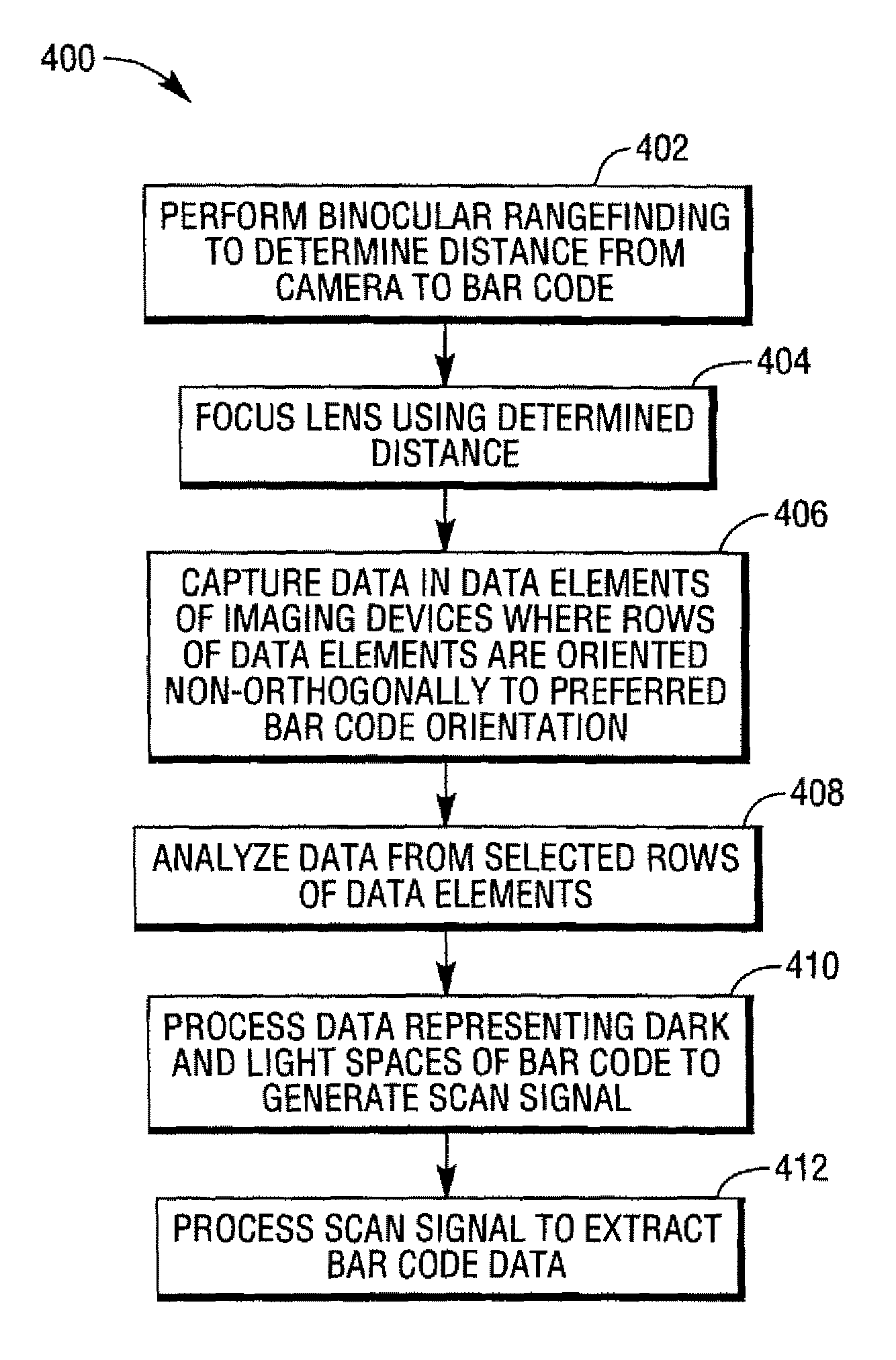
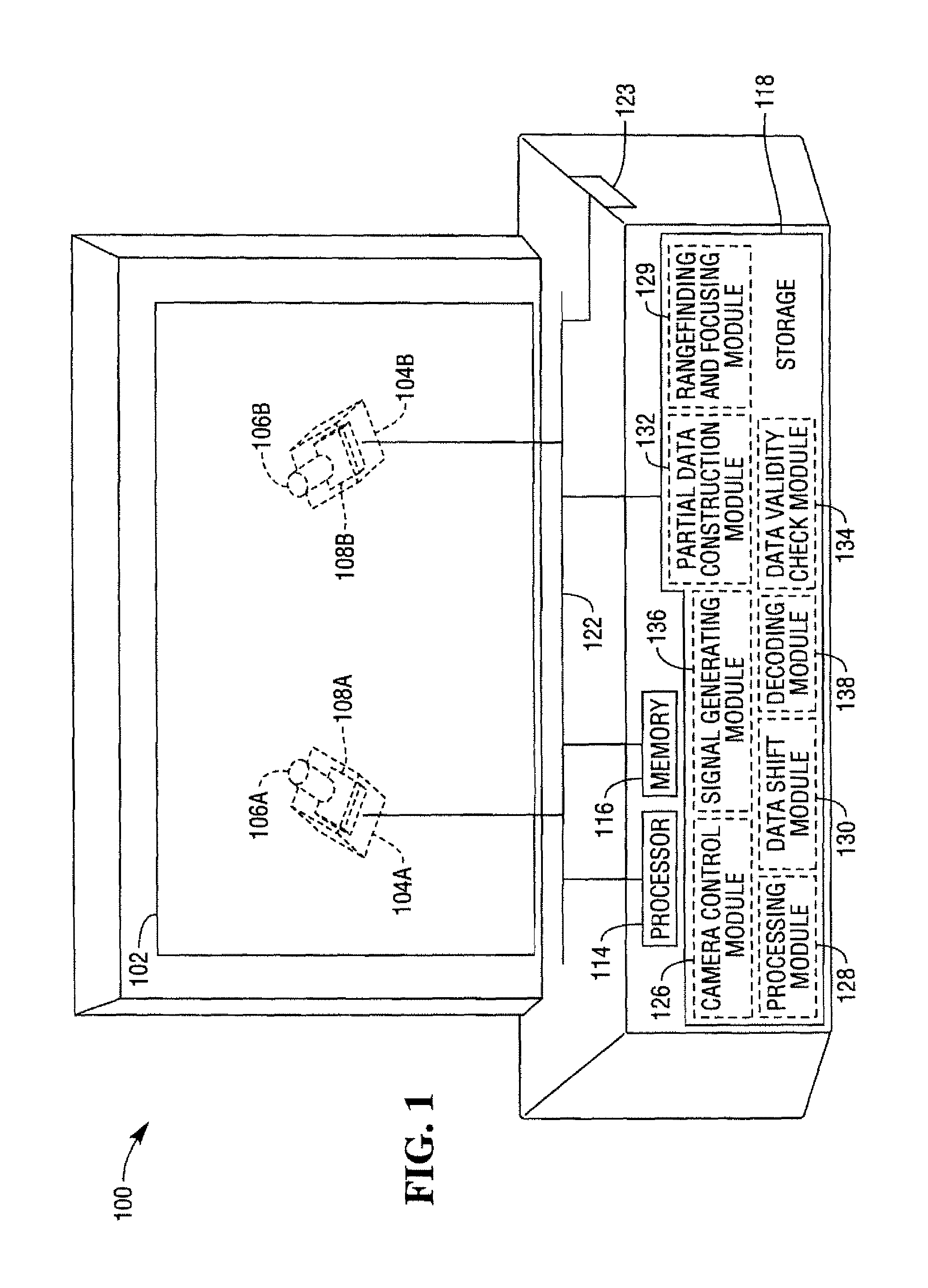
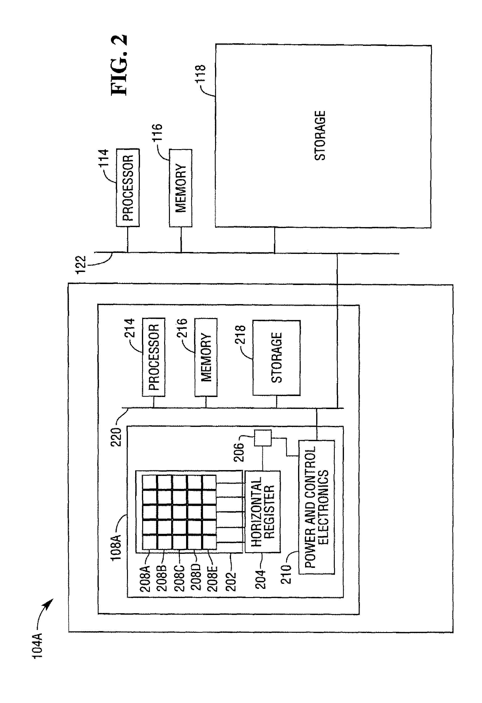
[0013]FIG. 1 illustrates a bar code scanner 100 according to an aspect of the present invention. The components of the scanner 100 are shown in block diagram form. The scanner 100 includes a vertical scan window 102 and first and second cameras 104A and 104B. While a vertical scan window is shown here as illustrative, a horizontal scan window may be employed as an alternative or in addition to the horizontal scan window 102.

[0014]The cameras 104A and 104B are digital cameras including lenses 106A and 106B, and imaging devices 108A and 108B, respectively. The cameras 104A and 104E are oriented such that the imaging devices are at an angle to a preferred orientation for a bar code presented at the scan window 102. A bar code in its preferred orientation of presentation will be presented in either a horizontal or vertical orientation, so the camera 104A is oriented at an angle of +45° from horizontal, and the camera 104B is oriented at an angle of −45° from horizontal. These orientatio...


PUM


Abstract

Improved systems and techniques for imaging bar code processing. One or more cameras are deployed in a bar code scanner, oriented so that an imaging device of each camera is oriented such that rows of data elements in the imaging device are oriented nonorthogonally with respect to a preferred orientation of a bar code. One or more imaging devices captures bar code data representing light and dark spaces of the bar code. The captured bar code data is analyzed to create one or more rows of data completely transecting the bar code, and the rows of data are processed to generate a scan signal which is in turn processed to extract bar code data.

Description

FIELD OF THE INVENTION[0001]The present invention relates generally to improved systems and techniques for bar code scanning. More particularly, the invention relates to improved systems and techniques for imaging bar code scanning including capturing data using imaging devices oriented such that the rows of data elements of the imaging device are nonorthogonal to preferred orientations for presentation of bar codes.BACKGROUND OF THE INVENTION[0002]With the increasing prevalence and capability of digital imaging techniques, imaging bar code scanning is gaining increasing interest as a mechanism for bar code scanning. Imaging scanning allows for significant simplification of scanner design and construction by avoiding complex laser and optical components used in conventional bar code scanners.[0003]Conventional laser bar code scanners, particularly pass by scanners, frequently provide numerous differently oriented scan lines, so that one or more scan lines can be counted on to inters...

Claims


Application Information

Patent Timeline
Patent Type & Authority Patents(United States)
IPC IPC(8): G06K7/10
CPCG06K7/10722G06K7/10851
Inventor DETWILER, PAUL OLIVERROQUEMORE, JOHN PETER
Owner NCR VOYIX CORP
Why Eureka
Try Eureka