
Method and apparatus to enhance oil recovery in wells

a well and oil recovery technology, applied in the direction of wellbore/well accessories, drilling pipes, drilling casings, etc., can solve the problems of reducing the mooring time of the vessel, affecting the mooring speed of the vessel, so as to reduce the mooring time and rapid unloading volume

Inactive Publication Date: 2013-07-23
SMITH DAVID RANDOLPH
View PDF12 Cites 3 Cited by
  • Summary
  • Abstract
  • Description
  • Claims
  • Application Information

AI Technical Summary

Benefits of technology

This patent text describes a method for using cryogenic pumps to quickly unload liquefied natural gas (LNG) from tankers offshore. This can help to reduce the time it takes to moor the vessels. The use of high-rate cryogenic turbo-pumps allows for the rapid unloading of large volumes of LNG. The technical effect of this patent is faster and more efficient ship unloading using cryogenic pumps.

Problems solved by technology

As such, over a period of time of extraction, the reservoir pressure becomes insufficient to force hydrocarbon fluids from the reservoir into the well.
Nevertheless, over fifty percent of the cost when using carbon dioxide to flood the well is the initial purchase of the carbon dioxide.
Further, the use of carbon dioxide in EOR methods has other disadvantages.
For example, once carbon dioxide is injected into an injection well, it cannot be recovered and resold.
Moreover, it causes formation of carbonic acid in water that can lead to corrosions of pipes and other equipment.
Further, it is difficult to inject gases into the reservoir, as it requires large high pressure compressors and prime movers at or near the wellbores.
It is costly to construct the required compressor injection facilities at each EOR site, and it is even more cost limiting when the EOR site is offshore because the compressors and prime movers would have to be located on the offshore platforms where space is expensive and limited.
Further, currently, the oil and gas industry has many known reservoirs of natural gas that are stranded because the reservoirs are geographically located far from a commercial markets.
The commercial activities, e.g., sales, of the produced cryogenic fluid, LNG, is limited in the world today because the markets for such LNG requires costly cryogenic facilities to receive and or re-gasify the cryogenic liquids at the destination market.
These receiving stations at the destination market, or re-gasification stations, are expensive and require LNG carrying ships to come into ports and near populated areas to discharge their cryogenic cargo.
The regassification facilities are often perceived as a potential health hazard; hence, public support for such facilities is difficult to obtain.

Method used


Image

  • Method and apparatus to enhance oil recovery in wells
  • Method and apparatus to enhance oil recovery in wells
  • Method and apparatus to enhance oil recovery in wells

Examples


Embodiment Construction

[0029]As used herein, “surface” refers to locations at or above the surface of the Earth, ice, ocean bottom, river bottom, lake bottom, and / or body of water, such as a lake, river, or ocean.

[0030]As used herein, “fluid” refers to substance that continually deforms and / or flows under an applied shear stress. This term includes gases and liquids.

[0031]As used herein, “cryogenic” refers to a liquid that boils, i.e., changes from a liquid to a gas, at temperatures less than about 110 Kelvin (K) at atmospheric pressure, such as hydrogen, helium, nitrogen, oxygen, air, or methane (natural gas).

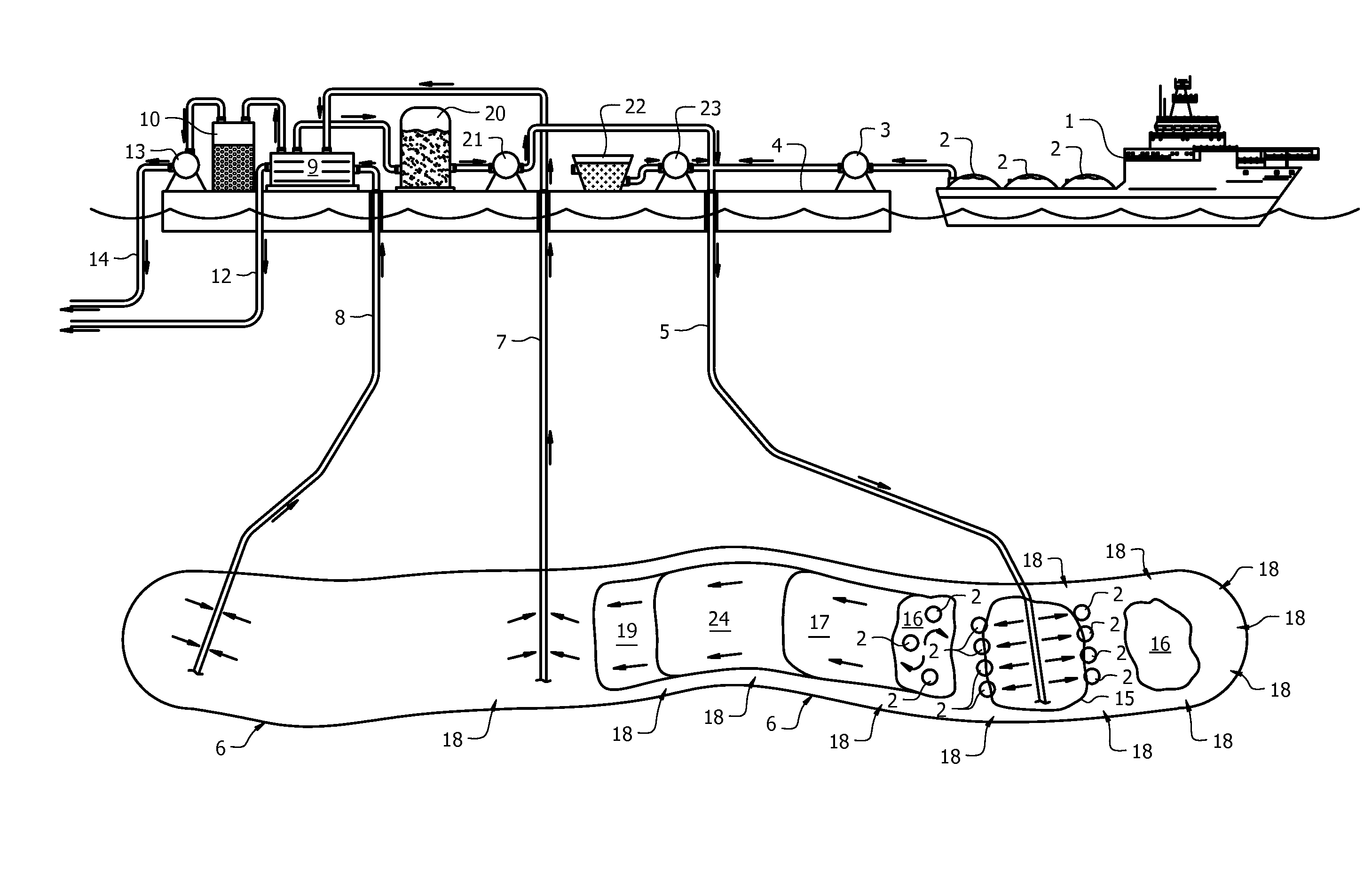
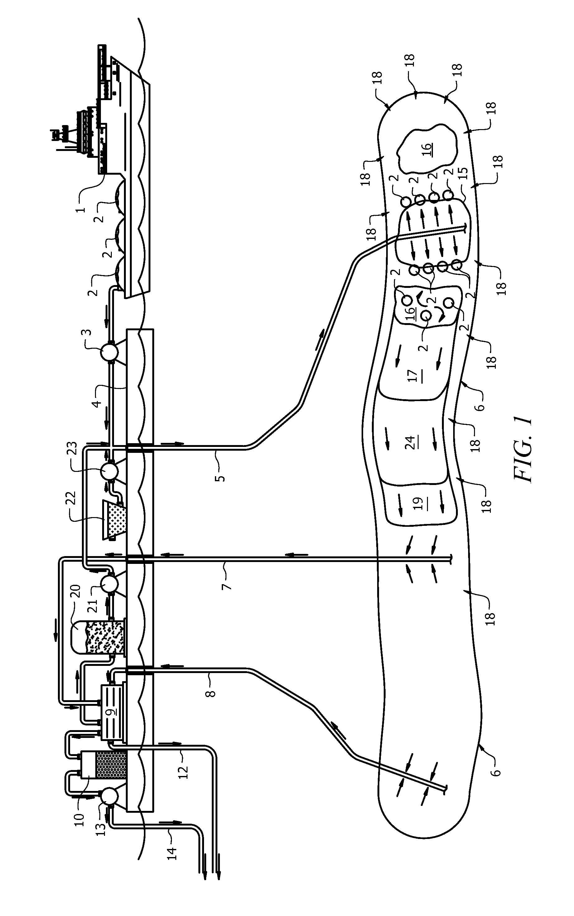
[0032]FIG. 1 shows a schematic of a system that uses a cryogenic fluid to enhance the recovery of oil from a reservoir. In FIG. 1, LNG ship 1 transports liquefied natural gas 2 from a LNG fabrication source to offshore oil platform 4. While FIG. 1 depicts transportation of LNG 2 by ship 1 to offshore platform 4, it is envisioned that other embodiments include transport of LNG 2 by truck to wellbores...


PUM


Abstract

A method and apparatus for the enhanced recovery of hydrocarbon fluids from subterranean reservoirs using cryogenic fluids. Using the Earth's geothermal energy to warm cryogenic flood fluids injected into subterranean reservoirs, the pressure within the subterranean reservoir is increased. This rise in pressure due to the injection of the cryogenic fluid leads to the production of fluids from to the subterranean reservoirs.

Description

CROSS-REFERENCE TO RELATED APPLICATIONS[0001]This Application claims the benefit of U.S. Provisional Application No. 61 / 170,966 filed on Apr. 20, 2009, which is incorporated herein in its entirety.TECHNICAL FIELD[0002]The present invention provides a method for enhanced oil recovery using cryogenic fluids. In particular, cryogenic fluids are injected into subterranean reservoirs to enhance the recovery of oil.BACKGROUND OF THE INVENTION[0003]In recent years, the demand for oil and natural gas has increased. The increase in demand for oil and natural gas is driving the oil and gas industry to produce more oil and natural gas using more cost efficient and effective techniques. Extracting subterranean fluids from depleted oil and gas reservoirs with new means is needed.[0004]Generally, when extracting oil and natural gas from subterranean reservoirs, the skilled artisan must consider the properties of the reservoir, the types of fluids present in the reservoir, and the physical and che...

Claims


Application Information

Patent Timeline
Patent Type & Authority Patents(United States)
IPC IPC(8): E21B43/24E21B43/16
CPCE21B43/16E21B43/24E21B43/166
Inventor SMITH, DAVID RANDOLPH
Owner SMITH DAVID RANDOLPH
Learn More