Method for controlling a drive train

a technology of drivetrain and control mechanism, which is applied in the direction of hybrid vehicles, electric propulsion mounting, transportation and packaging, etc., can solve the problems of affecting the shifting process, affecting and taking a comparatively long time. achieve the effect of speeding up and increasing the comfort of the gear shi

Inactive Publication Date: 2013-07-16
ZF FRIEDRICHSHAFEN AG
View PDF19 Cites 2 Cited by
  • Summary
  • Abstract
  • Description
  • Claims
  • Application Information

AI Technical Summary

Benefits of technology

[0013]Accordingly, the purpose of the present invention is to speed up and increase the comfort of a gearshift in a semi-automatic transmission that is arranged in a drive-train of a motor vehicle of the type described at the start, having an internal combustion engine, an electric machine and an automated friction clutch.
[0014]The invention is based on the recognition that an electric machine in driving connection with the driveshaft of the internal combustion engine can be used during a shifting process for a short time in generator operation and / or motor operation to assist and speed up the load reduction of the internal combustion engine at the beginning of a shifting process, the load increase at the end of a shifting process, and with the friction clutch at least partially closed, to synchronize the target gear during an shifting process.
[0015]As is known, in an electric machine the functions of a conventional electric motor and that of a conventional generator are combined in a single aggregate. An electric machine can be in drive connection, via a transmission such as a spur gear system or a wrap-around transmission, with the driveshaft of the internal combustion engine, or it can be connected directly thereto. Thus, the use of an electric machine saves weight and fitting space and reduces the complexity of the internal combustion engine. In addition, an electric machine can be used for actively damping typical rotational fluctuations of a piston internal combustion engine.

Problems solved by technology

Although a gearshift controlled in such a manner takes place relatively comfortably and with low wear, it takes a comparatively long time and entails a relatively long interruption of the traction or thrust force.
Such control methods have the disadvantage that the load reduction of an internal combustion engine at the beginning of a shifting process, the load increase of an internal combustion engine at the end of a shifting process, and the changing of the speed of an internal combustion engine to the synchronous speed of the target gear, take place relatively slowly because of the high moment of inertia of the internal combustion engine and its indirect control by means of the ignition and / or the fuel injection, so the time taken for the shifting process concerned is made longer.
Furthermore, due to the control sequences of the internal combustion engine and the friction clutch during a shifting process torque peaks and speed surges can occur, which adversely affect the shifting or driving comfort of the motor vehicle concerned.

Method used


Image

  • Method for controlling a drive train
  • Method for controlling a drive train
  • Method for controlling a drive train

Examples


Embodiment Construction

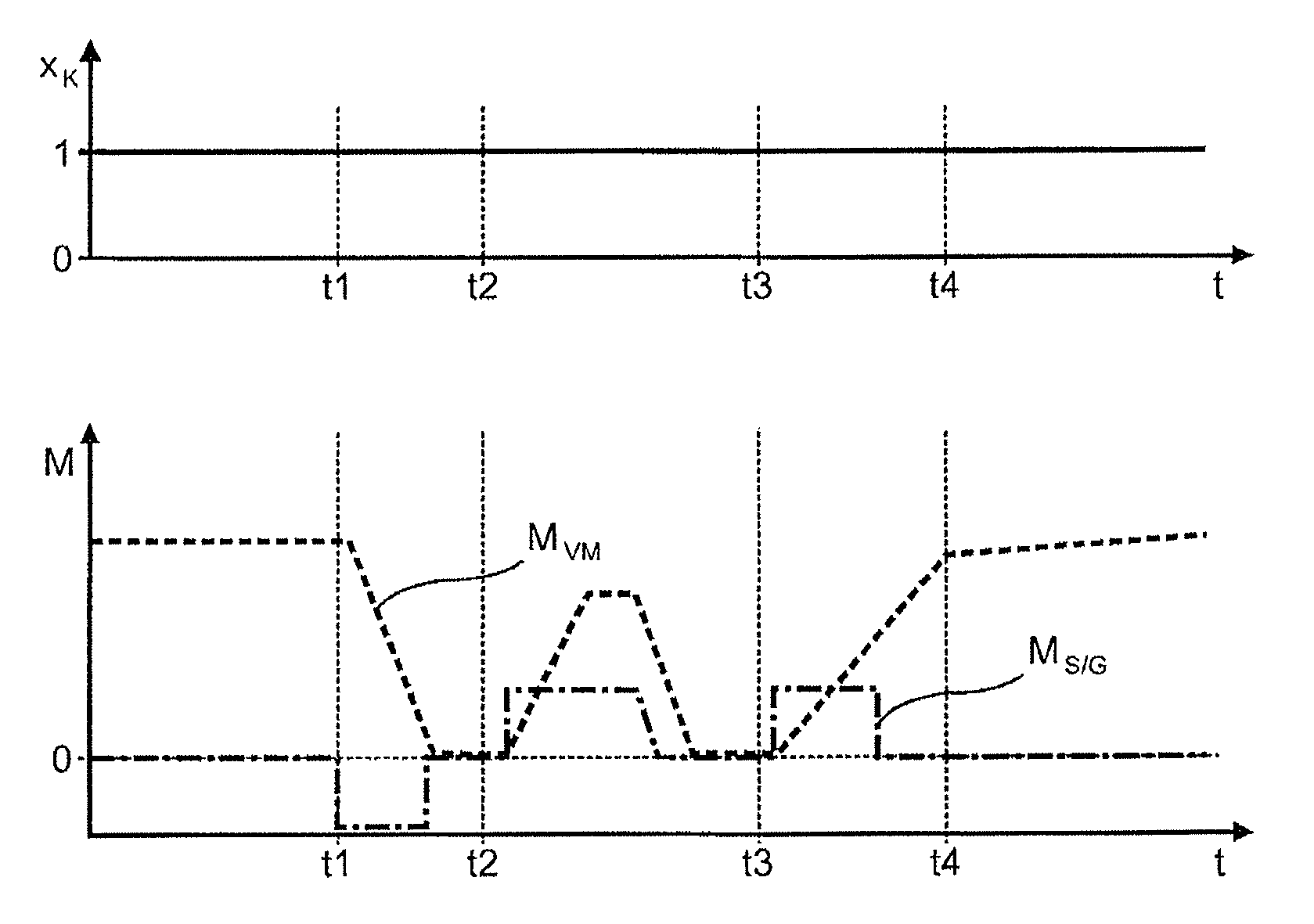
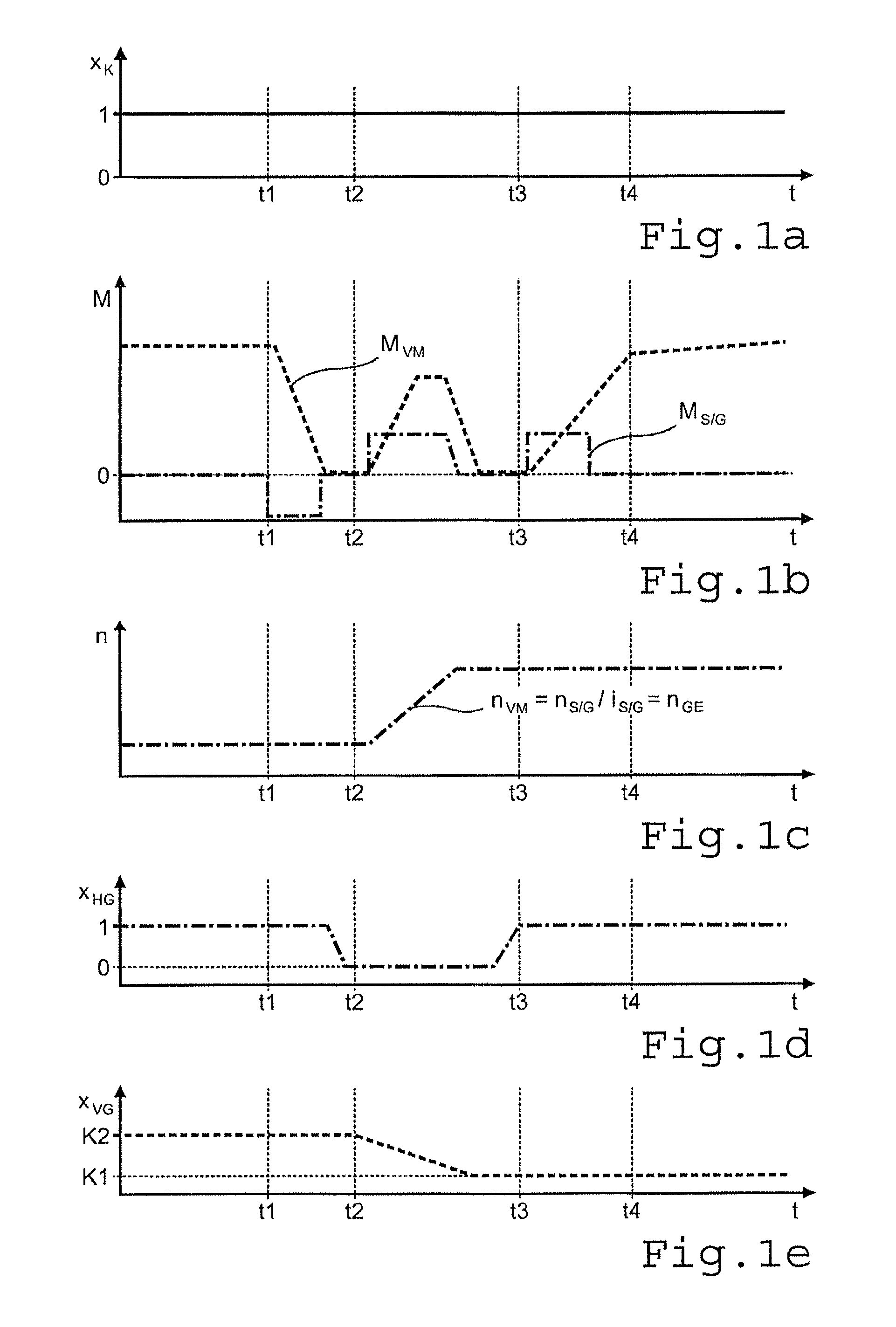
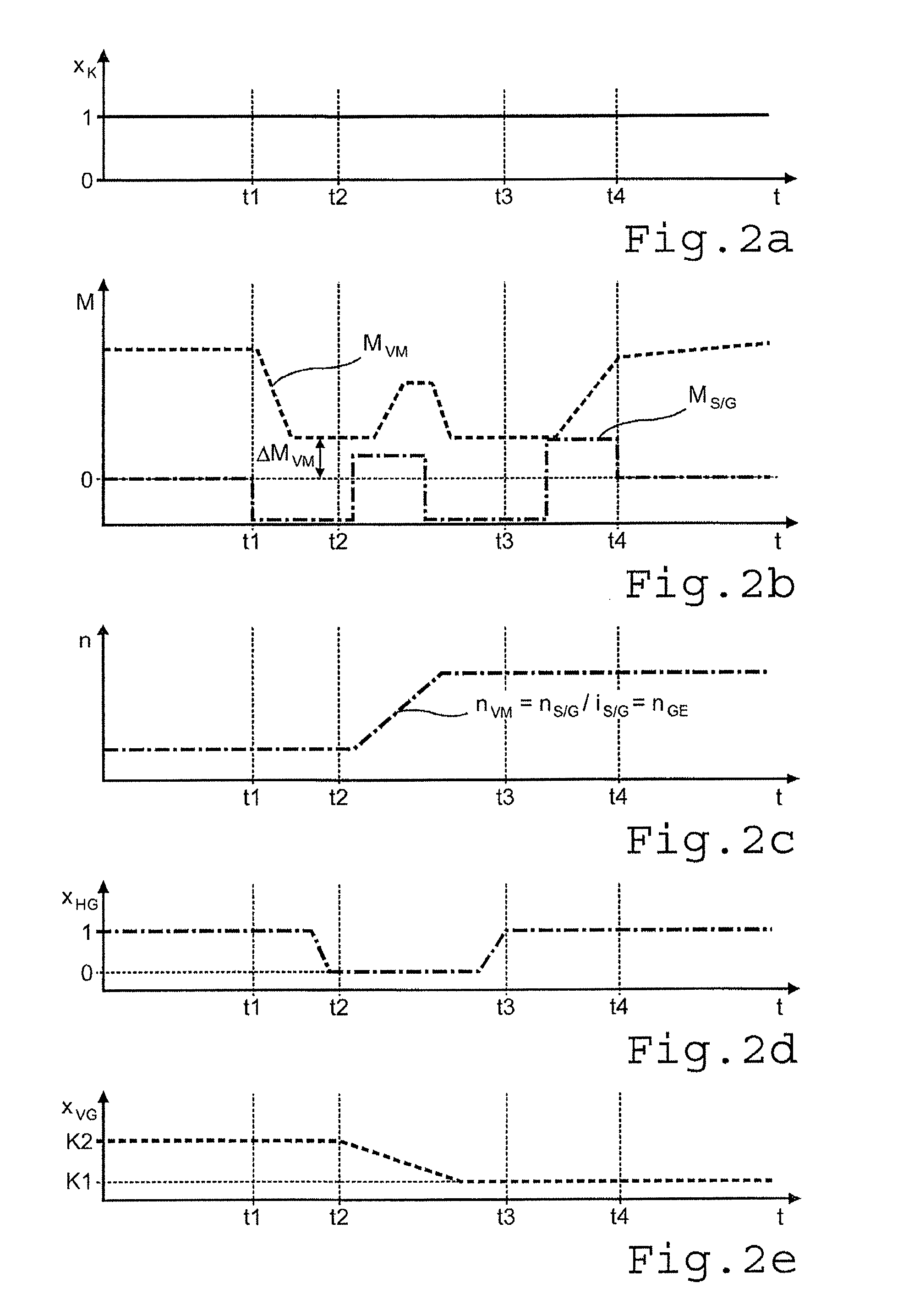
[0076]Below, the above shifting processes of a group transmission comprising a multi-stage main transmission HG and a two-stage splitter group VG connected upstream therefrom, and whose input shaft GE can be connected by an automated friction clutch K to the driveshaft of an internal combustion engine VM which is in driving connection with an electric machine S / G, are explained with reference to the diagrams of FIG. 1 to FIG. 4. The structure of a group transmission of this type can be seen for example in DE 10 2007 010 829 A1 (see FIG. 1a and FIG. 1b therein).

[0077]The present diagrams of FIG. 1 to FIG. 4 each show in part a) the time variation of the degree of closure xK(t) of the friction clutch K, in part b) the torque variation MVM(t) of the internal combustion engine and the torque variation MS / G(t) of the electric machine, in part c) the speed variation nVM(t) of the internal combustion engine and if needs be also the speed variation nGE(t) of the transmission input shaft, in...


PUM


Abstract

A method of controlling a drive-train of a motor vehicle, which comprises an internal combustion engine with a driveshaft, an electric machine in driving connection with the driveshaft of the internal combustion engine, a semi-automatic transmission with an input shaft and a plurality of gears that can be engaged selectively, and an automated friction clutch arranged between the driveshaft of the internal combustion engine and the input shaft of the transmission, such that a gearshift of the transmission occurs in combination with suitable control of the internal combustion engine while the friction clutch is at least partially and / or briefly engaged. To speed up the shifting process and to attenuate torque and speed surges during the shifting process, the electric machine is operated briefly as a generator and / or as a motor.

Description

[0001]This application claims priority from German patent application serial no. 10 2010 043 590.2 filed Nov. 9, 2010.FIELD OF THE INVENTION[0002]The invention concerns a method for controlling a drive-train of a motor vehicle.BACKGROUND OF THE INVENTION[0003]A gearshift in a semi-automatic change-speed transmission usually takes place in such manner that during a load reduction of the internal combustion engine the torque (motor torque) delivered by or taken up from the internal combustion engine is decreased and a friction clutch is opened, whereby the transmission becomes largely free from load. Then, the currently engaged gear carrying the load before the gearshift is disengaged, and the target gear to be engaged is synchronized and then engaged. To synchronize the target gear the rotational speed of the transmission input shaft is reduced for an upshift and increased for a downshift, so that the two clutch halves of the gear clutch of the target gears are rotating at much the s...

Claims


Application Information

Patent Timeline
Patent Type & Authority Patents(United States)
IPC IPC(8): B60W10/02B60W10/06B60W10/08B60W10/10
CPCB60K6/48B60W10/02B60W10/08F16H61/0403B60W2710/083Y10T477/26F16H2061/0422F16H2061/0433Y02T10/6221Y10T477/23F16H61/70Y02T10/62
Inventor GLUCKLER, JOHANNESMAIER, ALEXANDERHUNOLD, BERNARD
Owner ZF FRIEDRICHSHAFEN AG
Why Eureka
Try Eureka