
Portable drip containment device apparatus and method

a technology of drip containment device and container, which is applied in the direction of mechanical equipment, manufacturing tools, transportation and packaging, etc., can solve the problems of affecting the environment where such equipment is located, requiring one or more relatively cumbersome installation, assembly, adjustment, and disassembly procedures in use, and achieving sufficient excess width and length, to protect the bolster member from abrasion or other damag

Active Publication Date: 2013-07-09
MATSON INC
View PDF8 Cites 7 Cited by
  • Summary
  • Abstract
  • Description
  • Claims
  • Application Information

AI Technical Summary

Benefits of technology

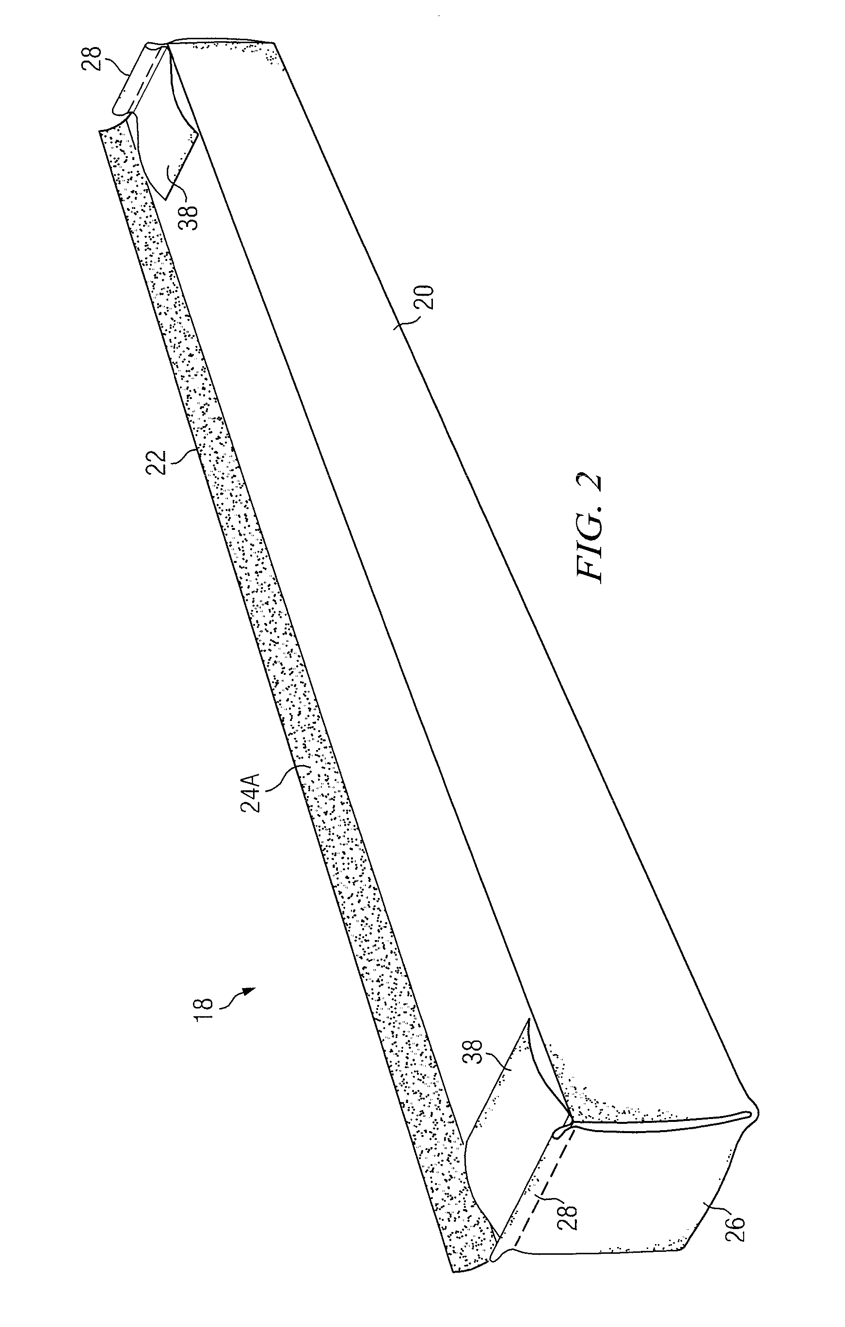
The patent text describes a method for making a protective sleeve for a bolster member. The method involves precutting the bolster member to a standard length, adding a coated fabric around the bolster member to create a side seam and a package wrap end panel, and then enclosing the bolster member within the sleeve to prevent liquids from entering and protect it from damage. The technical effect of this method is to create a more robust and durable protective cover for the bolster member, which can withstand abrasion and damage during shipment and use.

Problems solved by technology

In one example, machinery used for drilling oil and gas wells, especially those used in a process called hydraulic fracturing (often: “fracing”) presents a challenge to avoid spills on the ground in such installations.
Even though well-thought-out and carefully implemented procedures for handling such materials may be in place and conscientiously used, accidents can and do occur that may result in harm to the surroundings where such equipment is located.
However, a paved surface is a permanent fixture that entails substantial expense to provide and thus is not suitable for machinery or installations where such equipment is used that is moved from place to place.
These have the disadvantage of requiring one or more of relatively cumbersome installation, assembly, adjustment, and disassembly procedures in use, require tools during use, or require a source of compressed air, for example, to inflate supporting structural elements of the containment unit.

Method used


Image

  • Portable drip containment device apparatus and method
  • Portable drip containment device apparatus and method
  • Portable drip containment device apparatus and method

Examples


Embodiment Construction

Introduction

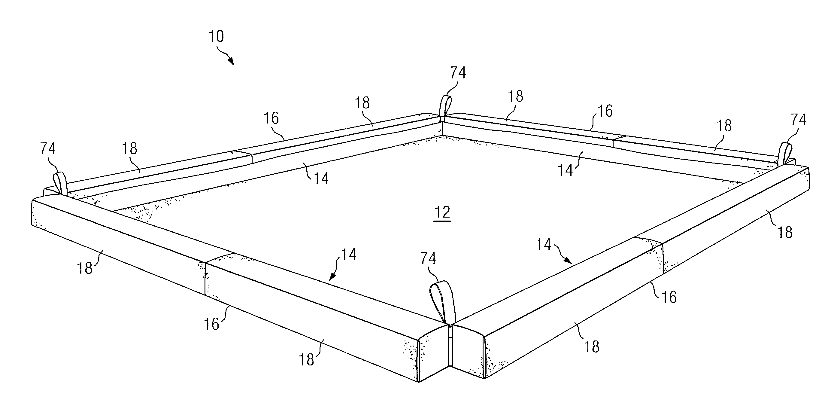
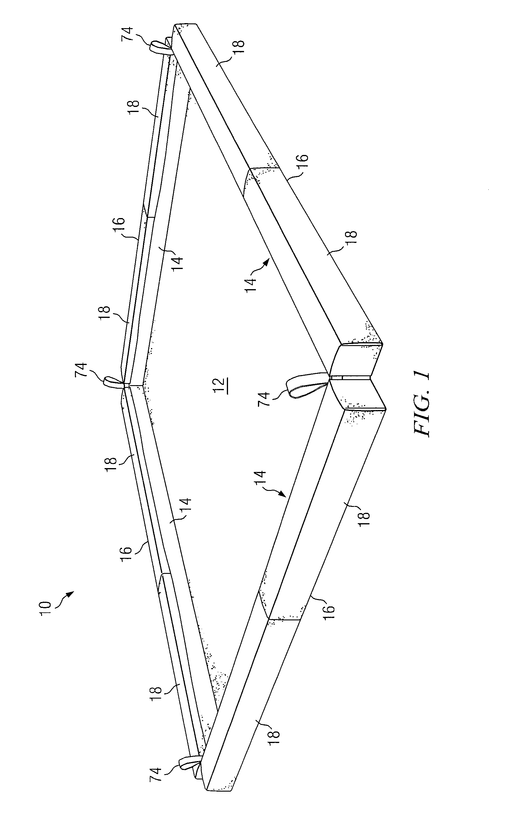
[0033]A portable drip or spill containment device (also called a containment tray) is disclosed that provides an advance in the state of the art and combines low cost, light weight, a minimum of component parts, ease of portability, storage, installation without tools, and reuse. Unlike prior art spill containment devices, the containment device designed according to the present invention employs flexible side walls supported by fully deformable, resilient bolsters to permit wheeled vehicles to drive or roll unto the device without manipulation or maneuvering of the side wall structures. The device may be easily assembled and disassembled without tools, is portable, and may be reused many times over. When folded and rolled up, the containment tray is portable and can be carried and installed by one person. The bolster structure is formed of a plurality of resilient bolster segments that are uniform in shape and readily stackable in a small footprint. These modular featur...


PUM

PropertyMeasurementUnit
perimeteraaaaaaaaaa
lengthsaaaaaaaaaa
lengthsaaaaaaaaaa

Abstract

A portable drip containment device comprises a tray formed of fuel and chemical resistant fabric. Side walls of the tray are supported by removable bolster segments formed of resilient open cell foam members enclosed within sleeves. The bolster segments are wrapped within a flap of material extending from under the side wall of the tray and around the bolster segments to secure them to the side walls. The outer edge or end of the flap is secured to the side wall. The bolstered side walls may be repeatedly driven across by industrial vehicles without harming the bolster or side wall. The modular bolster segments may be removed and easily stacked, and the tray folded and rolled into a compact modular form, for transport, storage, and reuse of the portable containment tray.

Description

RELATED APPLICATION[0001]This application claims priority to U.S. Provisional Patent Application Ser. No. 61 / 495,141 filed Jun. 9, 2011 and entitled PORTABLE DRIP CONTAINMENT DEVICE.BACKGROUND OF THE INVENTION[0002]1. Field of the Invention[0003]The present invention generally relates to spill containment methods and more particularly to portable apparatus for catching and containing spills of toxic or environmentally hazardous materials from industrial vehicles and related equipment.[0004]2. Background of the Invention and Description of the Prior Art[0005]In a number of industrial processes, machine equipment that includes apparatus that transports, dispenses, or utilizes materials—liquid or dry aggregate—that may be toxic to living things or otherwise harmful to the environment requires some form of protective or containment device or method to avoid contamination thereof when the vehicle or other machine is not in motion. In one example, machinery used for drilling oil and gas w...

Claims


Application Information

Patent Timeline
Patent Type & Authority Patents(United States)
IPC IPC(8): B65D1/34
CPCF16N31/00F16N31/006Y10T29/49817Y10T29/4995Y10T29/49826Y10T29/49815
Inventor MATSON, MARK
Owner MATSON INC
Learn More