Ambulatory aid

a technology for ambulatory aids and wheelchairs, applied in the field of ambulatory aids, can solve problems such as easy falls by users

Inactive Publication Date: 2013-07-09
GENTRY WAY
View PDF11 Cites 8 Cited by
  • Summary
  • Abstract
  • Description
  • Claims
  • Application Information

AI Technical Summary

Benefits of technology

[0006]Therefore it is a primary object of the present invention to provide an ambulatory aid having a tight and firm structure for preventing looseness and instability at connection sites and providing higher safety.
[0008]By the insertion pins that fix the cushion unit, the support pole and the main rod, the structure of the assembly of the main rod, the support pole and the cushion unit is more firm. Thus the user will not fall down or lose body control due to movement of the assembly caused by damaged or loose structure when the ambulatory aid is pressed by a larger pressure.

Problems solved by technology

The user easily falls down.

Method used


Image

  • Ambulatory aid
  • Ambulatory aid
  • Ambulatory aid

Examples


Embodiment Construction

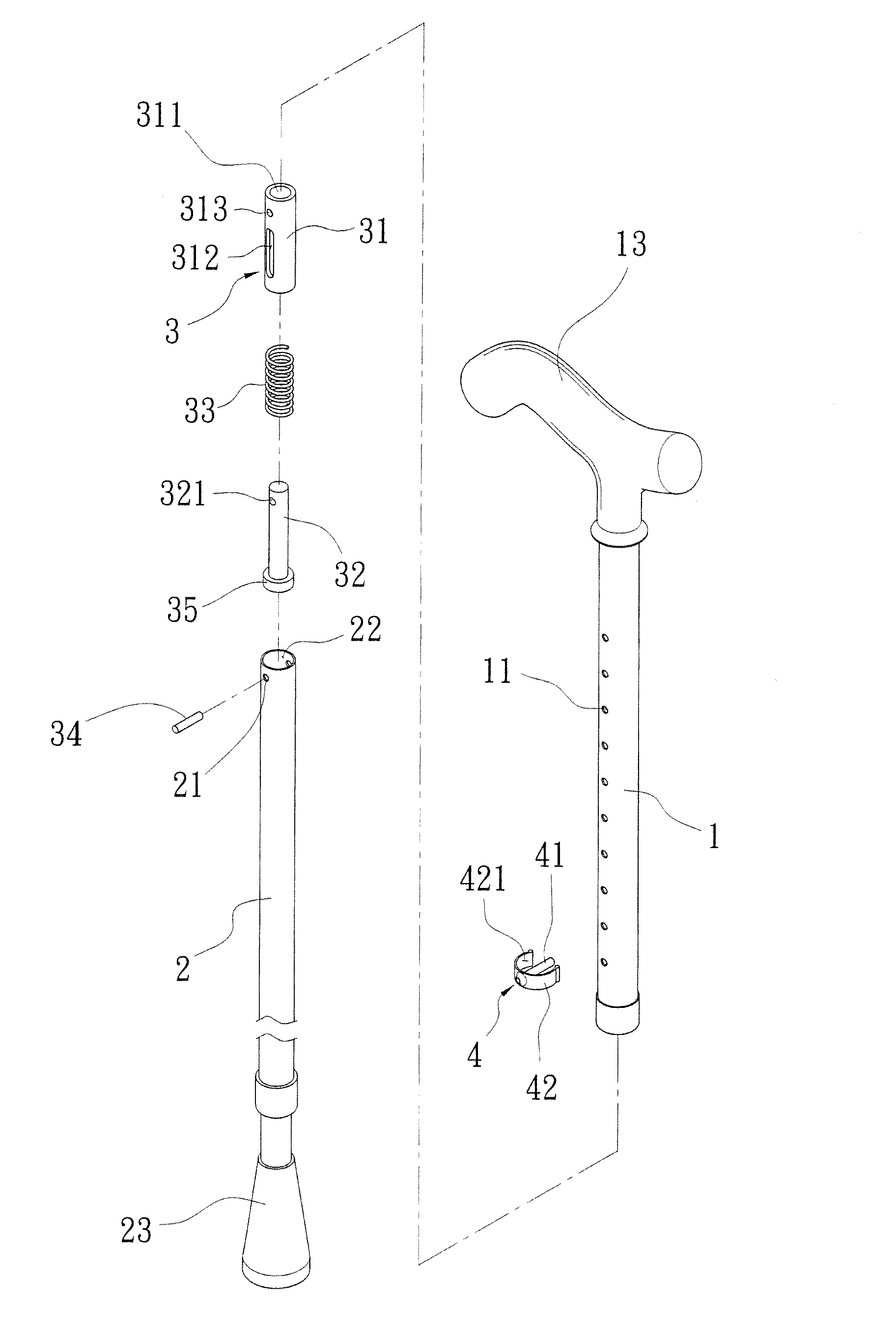
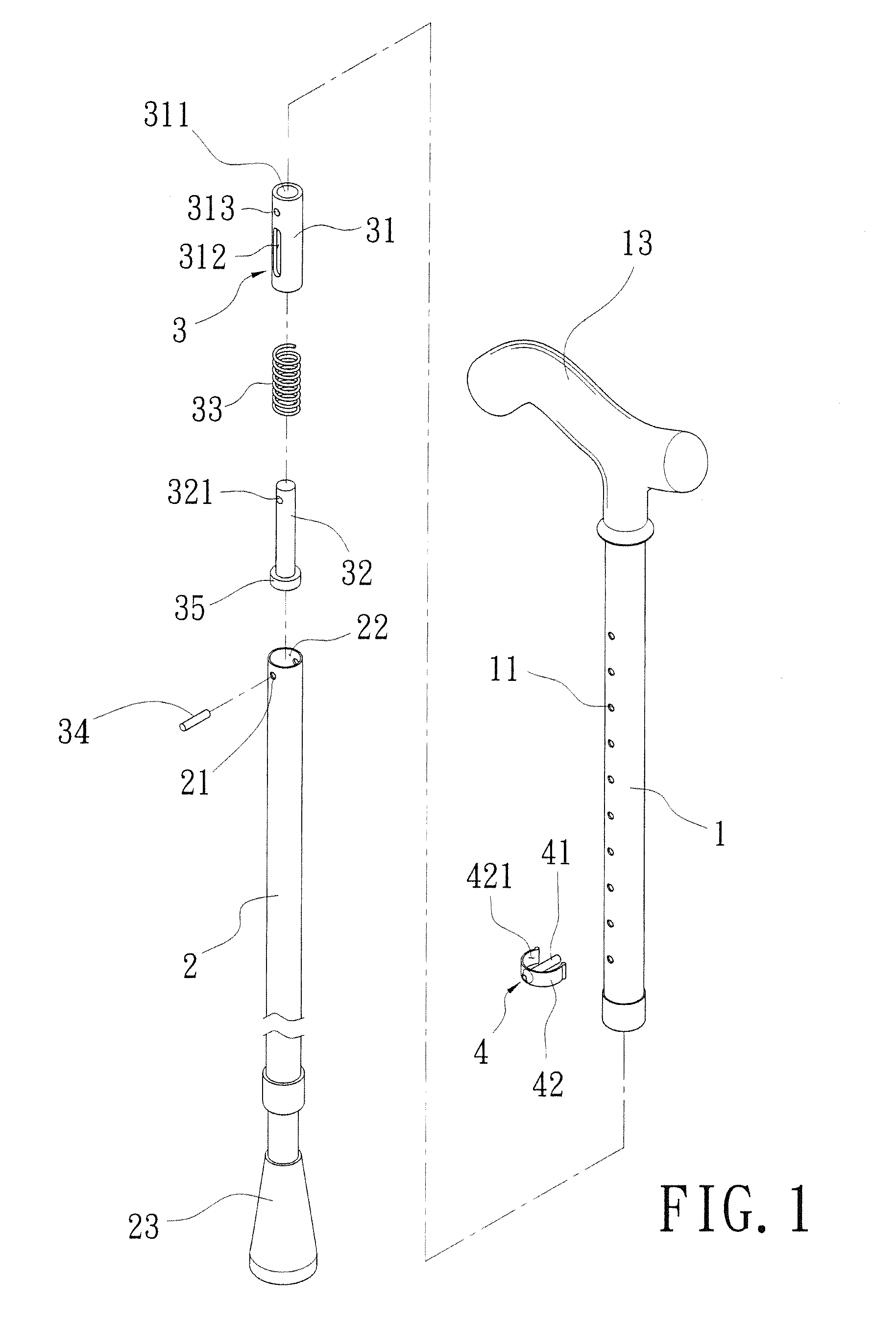
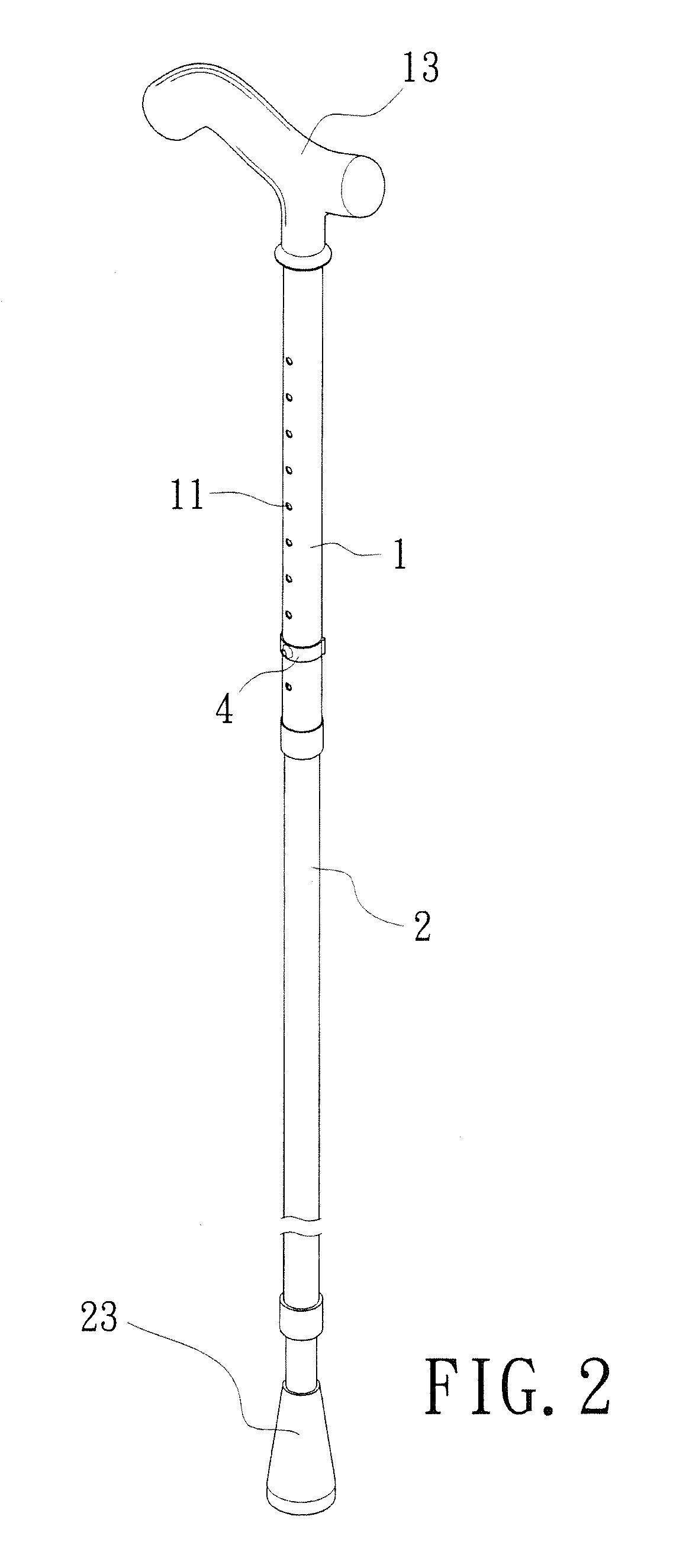
[0019]Refer from FIG. 1 to FIG. 3, an ambulatory aid according to the present invention includes a main rod 1, a support pole 2, a cushion unit 3 and a fixing unit 4.

[0020]The main rod 1 is a hollow tube and having a plurality of insertion holes 11 arranged vertically on two sides thereof. The insertion holes 11 communicate with a hollow part 12 of the main rod 1. A handle part 13 is arranged on the top of the main rod 1.

[0021]The support pole 2 is a hollow tube, connected with and sleeved in the main rod 1. Each of two sides of the support pole 2 is disposed with an insertion hole 21 that communicates with a hollow part 22 of the support pole 2. An anti-slip block 23 is disposed on a bottom of the support pole 2.

[0022]The cushion unit 3 is set between the main rod 1 and the support pole 2. The cushion unit 3 is composed of a hollow sleeve 31, an assembly rod 32 and an elastic body 33. The assembly rod 32 is mounted into a hollow part 311 of the sleeve 31. One end of the assembly ro...


PUM


Abstract

An ambulatory aid is revealed. The ambulatory aid includes a hollow main rod and a hollow support pole connected with each other, and a cushion unit therebetween. The main rod, the hollow support and the cushion unit all have insertion holes, aligned with each other. By insertion pins inserted into the insertion holes, the main rod, the hollow support and the cushion unit are assembled with each other. The structure of the assembly of the main rod, the hollow support and the cushion unit is more firm and tighter. When the ambulatory aid is pressed by a larger pressure, the assembly will not come loose and move around and the unstable walking stick makes the users fall down due to a loss of support.

Description

BACKGROUND OF THE INVENTION[0001]1. Field of the Invention[0002]The present invention relates to an ambulatory aid, especially to an ambulatory aid having a tight and firm structure for preventing instability and providing high safety.[0003]2. Description of Related Art[0004]Refer to FIG. 9, this is a walking stick for old people who have low-level moving activity due to poor physical function or people with wounded legs. The walking stick mainly includes a hollow main rod 6 and a support pole 7. A cushion unit 8 is arranged between the main rod 6 and the support pole 7. The cushion unit 8 consists of a sleeve 81, an assembly rod 82, an elastic body 83 and a support block 84. One end of the assembly rod 82 is connected to and fixed on the one end of the support pole 8 and the elastic body 83 is placed around the assembly rod 82 while the other end of the assembly rod 82 disposed with the support block 84 is mounted into a hollow part of the sleeve 81. Due to the support block 84, th...

Claims


Application Information

Patent Timeline
Patent Type & Authority Patents(United States)
IPC IPC(8): A45B9/00A61H3/02
CPCA45B9/00A61H3/00A61H2201/0192A45B2009/007A61H2003/0272A45B2009/005
Inventor HUNG, CHI-WEI
Owner GENTRY WAY
Why Eureka
Try Eureka