
Remote health monitoring system

a remote monitoring and physiologic technology, applied in the field of remote physiologic monitoring systems, can solve the problems of inability to use inability to rely on the patient to actuate the device and then send the data, and inability to achieve real-time analysis of patient data, etc., to achieve lower sampling rate, lower resolution, and high specificity

Active Publication Date: 2013-07-02
INFOBIONIC
View PDF140 Cites 228 Cited by
  • Summary
  • Abstract
  • Description
  • Claims
  • Application Information

AI Technical Summary

Benefits of technology

This method enables real-time, efficient analysis of patient data with reduced wireless channel utilization and lower power consumption, allowing for timely detection and verification of health anomalies while minimizing false positives and negatives.

Problems solved by technology

Holter monitors are relatively inexpensive, but they cannot be used for real-time analysis of patient data, because the data is analyzed hours, days or weeks after it has been collected.
Although such an event monitor can facilitate analysis of patient data more proximate in time to the patient-detected anomaly, relying on the patient to actuate the device and then send the data can be problematic.
However, these devices still rely on patients to send the recorded data for analysis, and there is still a delay between detection of a suspected arrhythmia and transmission of the data.
These MCT devices typically do not perform any ECG analysis of their own.
Although no patient-initiated action is required, the large amount of data transmitted by the MCT wireless devices congests the wireless channels used to convey the data.
Furthermore, a large amount of computational resources is required at the remote monitoring center to analyze the continuous stream of received data, especially when many patients are monitored by a single data center.

Method used


Image

  • Remote health monitoring system
  • Remote health monitoring system
  • Remote health monitoring system

Examples


Embodiment Construction

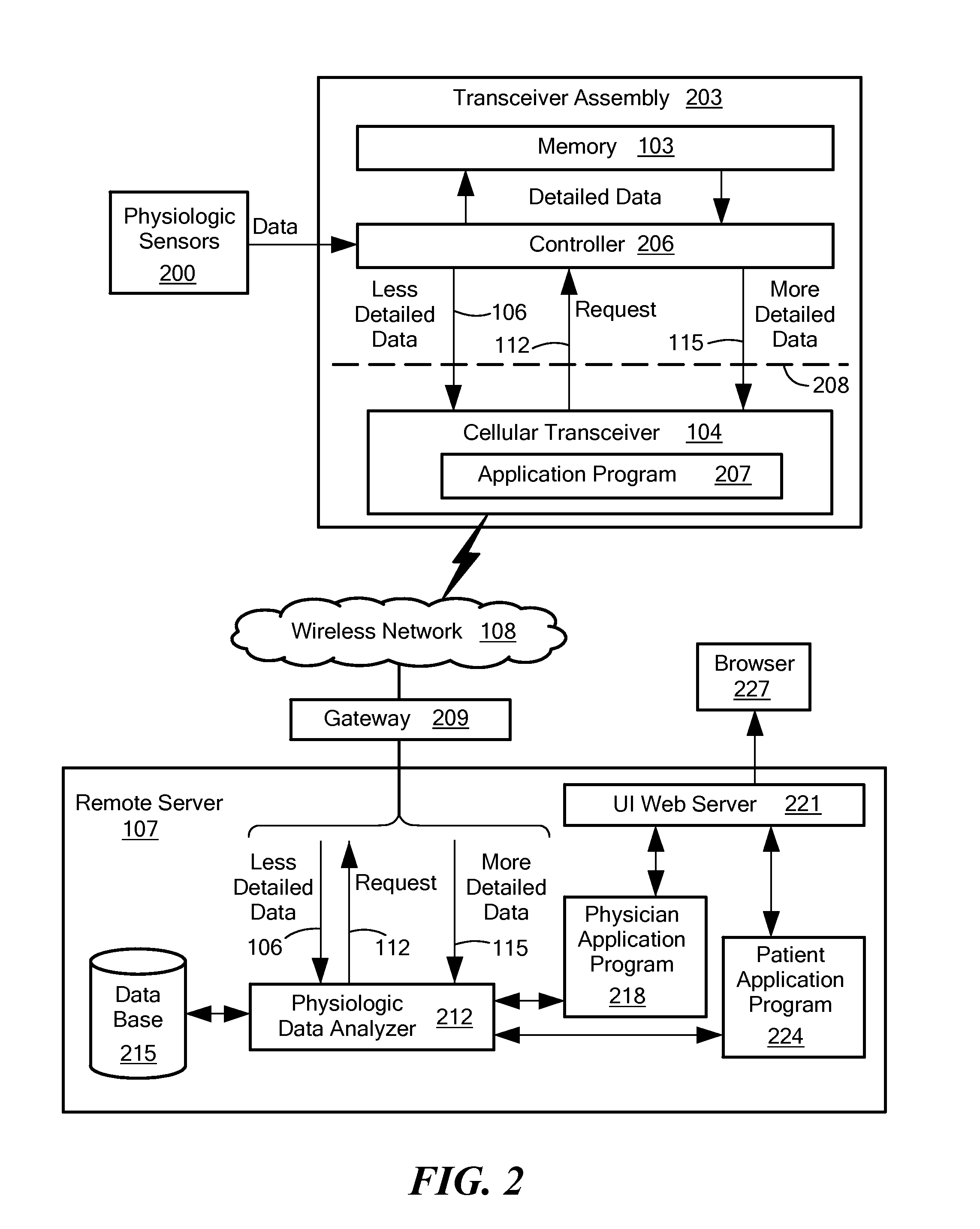
[0013]An embodiment of the present invention provides a system for remote physiologic monitoring of a body of a patient. The monitoring is performed in association with a remote server. The system includes a plurality of sensors and a transceiver assembly. Each sensor of the plurality of sensors configured to be coupled to the body of the patient to generate respective physiologic data about the body. The transceiver assembly includes a memory, a controller and a wireless transceiver. The transceiver assembly is communicatively coupled to the plurality of sensors. The transceiver assembly is configured to receive the physiologic data from the plurality of sensors. The transceiver assembly is also configured to store the received physiologic data in the memory. The stored data is referred to as “more detailed data.” The transceiver assembly is configured to send a subset of the received physiologic data (referred to as “less detailed data”), via the wireless transceiver, to the remot...


PUM


Abstract

A data collection system collects and stores physiological data from an ambulatory patient at a high resolution and / or a high data rate (“more detailed data”) and sends a low-resolution and / or downsampled version of the data (“less detailed data”) to a remote server via a wireless network. The server automatically analyzes the less detailed data to detect an anomaly. A two-tiered analysis is used, where the first tier is less specific than the second tier. If the less specific analysis detects or suspects the anomaly, the server signals the data collector to send more detailed data that corresponds to a time period associated with the anomaly. The more specific second tier analysis the more detailed data to verify the anomaly. The server may also store the received data and make it available to a user.

Description

CROSS REFERENCE TO RELATED APPLICATIONS[0001]This application claims the benefit of U.S. Provisional Patent Application No. 61 / 476,072, filed Apr. 15, 2011, titled “Remote Health Monitoring System,” the entire contents of which are hereby incorporated by reference herein, for all purposes.TECHNICAL FIELD[0002]The present invention relates to remote physiologic monitoring systems and, more particularly, to patient-worn remotely-controlled physiologic monitoring systems.BACKGROUND ART[0003]Remote monitoring of ambulatory patients enables doctors to detect or diagnose heart problems, such as arrhythmias, that may produce only transient symptoms and, therefore, may not be evident when the patients visit the doctors' offices. Several forms of cardiac event monitors have been used.[0004]A “Holter” monitor is worn by a patient and collects and stores data for a period of time, typically at least 24 hours, and in some cases up to two weeks. After the data has been collected, the Holter moni...

Claims


Application Information

Patent Timeline
Patent Type & Authority Patents(United States)
IPC IPC(8): A61N1/08A61B5/04G16H40/67
CPCA61B5/0006A61B5/14552A61B5/0205A61B5/08G06F19/3418G08B21/10Y02A90/10G16H40/67G08C17/02A61B5/00G01V1/00A61B5/0022A61B5/0002
Inventor FAHEY, MICHAEL
Owner INFOBIONIC
Learn More