Eureka AIR delivers breakthrough ideas for toughest innovation challenges, trusted by R&D personnel around the world.

Indexable milling insert for milling tools

a technology of inserts and milling tools, applied in the direction of shaping cutters, manufacturing tools, transportation and packaging, etc., can solve the problems of inability to efficiently and precisely machine materials, high cost of regrinding, and inability to use milling cutters, etc., and achieve good means of ramping operations

Inactive Publication Date: 2013-07-02
SANDVIK INTELLECTUAL PROPERTY AB
View PDF32 Cites 10 Cited by
  • Summary
  • Abstract
  • Description
  • Claims
  • Application Information

AI Technical Summary

Benefits of technology

[0016]In case of a great axial reach, it is important with rigid clamping of the milling insert, since it becomes more sensitive to cutting forces than in case of a normal axial reach. Yet an advantage of the invention is that it allows a great axial milling depth, since the combined effect of the support surfaces and the coupling structure entails that the milling insert is stably fixed, which counteracts that the milling insert tips during the milling operation.
[0017]An additional advantage of the present embodiment is that it may provide good means of carrying out ramping operations. Ramping operations are possible if the radial cutting depth does not exceed the insert width. Axial feed and the ramping capacity are limited by the distance between cutting edge and milling cutter body, as well as by the length of the axial cutting edge. Depending on how the cutting edge is formed, the described invention may result in the possibility of carrying out ramping operations.

Problems solved by technology

A disadvantage of solid shank-end mills is that they have to be reground when they have become worn and thereby no longer can machine the material efficiently and precisely.
The regrinding is often expensive since cemented carbide requires advanced grinding tools.
Another disadvantage of regrinding of the tools is that a milling cutter, which from the beginning has had a certain diameter, intended for a specific operation, for instance a certain groove width, gets a reduced diameter after grinding.
A shank-end mill provided with milling inserts has a higher machining capacity but is limited in the axial cutting depth by the length of the insert edge.
Long insert edges entail that the milling insert becomes more sensitive to cutting forces, thereby running the risk of being dislodged from its position.
Small screws or other fastening members are difficult to handle since they easily are dropped in the mounting of the milling inserts.
Small screws have also lower mechanical strength and are more difficult to screw in, since the threads and the screw head are more fragile and sensitive to the position of the screw in the threads.
If the screw enters obliquely into the screw hole, the risk is great that the threads are destroyed, which has the consequence that the screw is destroyed.
Also the threaded hole in the basic body may be damaged, which involves a great additional cost since the entire basic body may be needed to be replaced.
For axially mounted milling inserts, it may also be hard to get access for tools when the milling inserts are to be mounted.
Because of the diameter of the basic body, when small milling tools are concerned, also the number of milling inserts possible to mount becomes limited.
By the fact that the milling inserts are mounted tangentially in the basic body, the problem to access the screw by the tool becomes smaller.
However, the problem of milling cutters of small diameters (<25 mm diameter) remains, foremost the fact that the loose details become difficult to handle, as well as that small fastening members are sensitive in the mounting step and have lower mechanical strength.

Method used


Image

  • Indexable milling insert for milling tools
  • Indexable milling insert for milling tools
  • Indexable milling insert for milling tools

Examples


Embodiment Construction

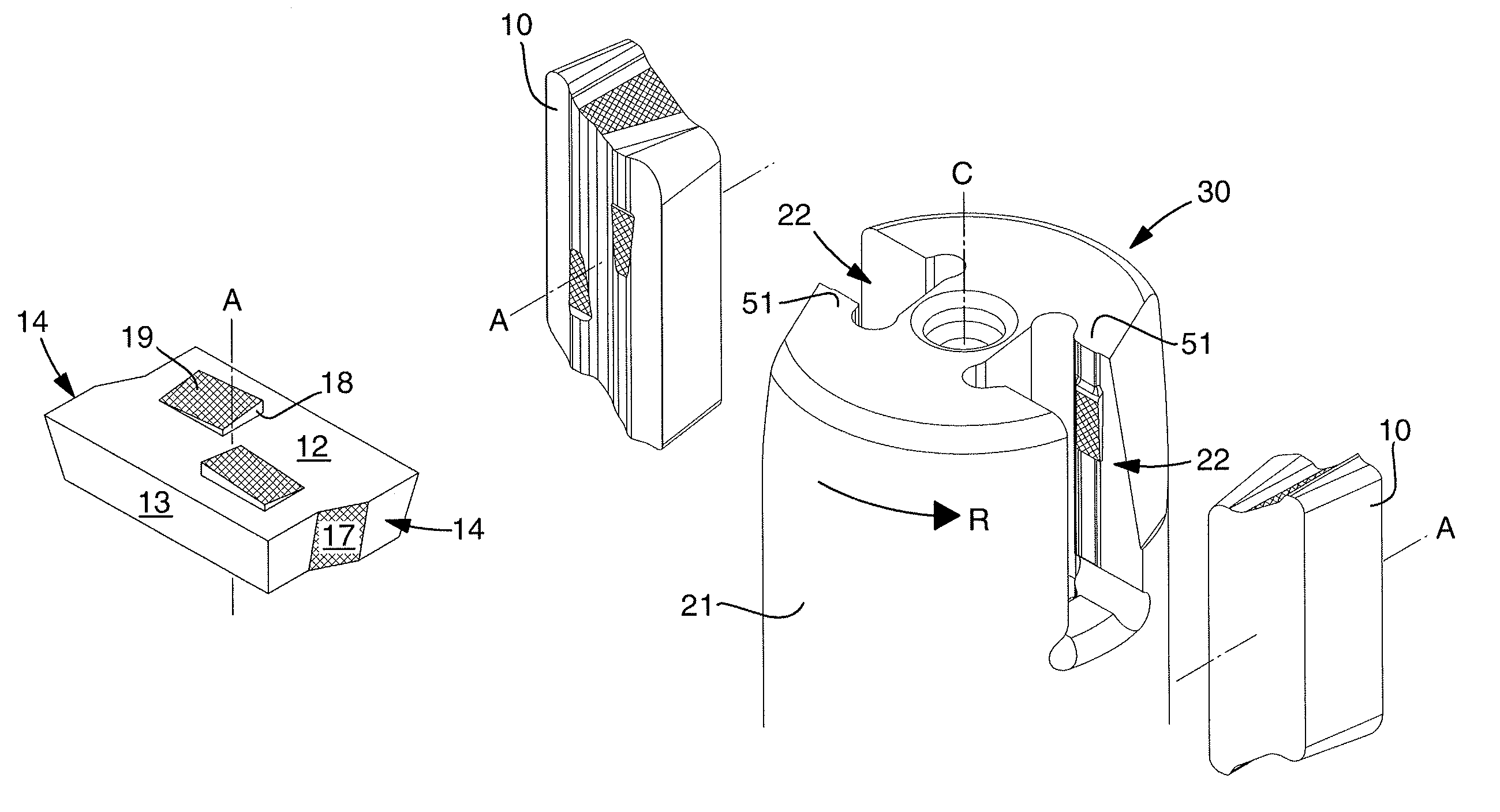
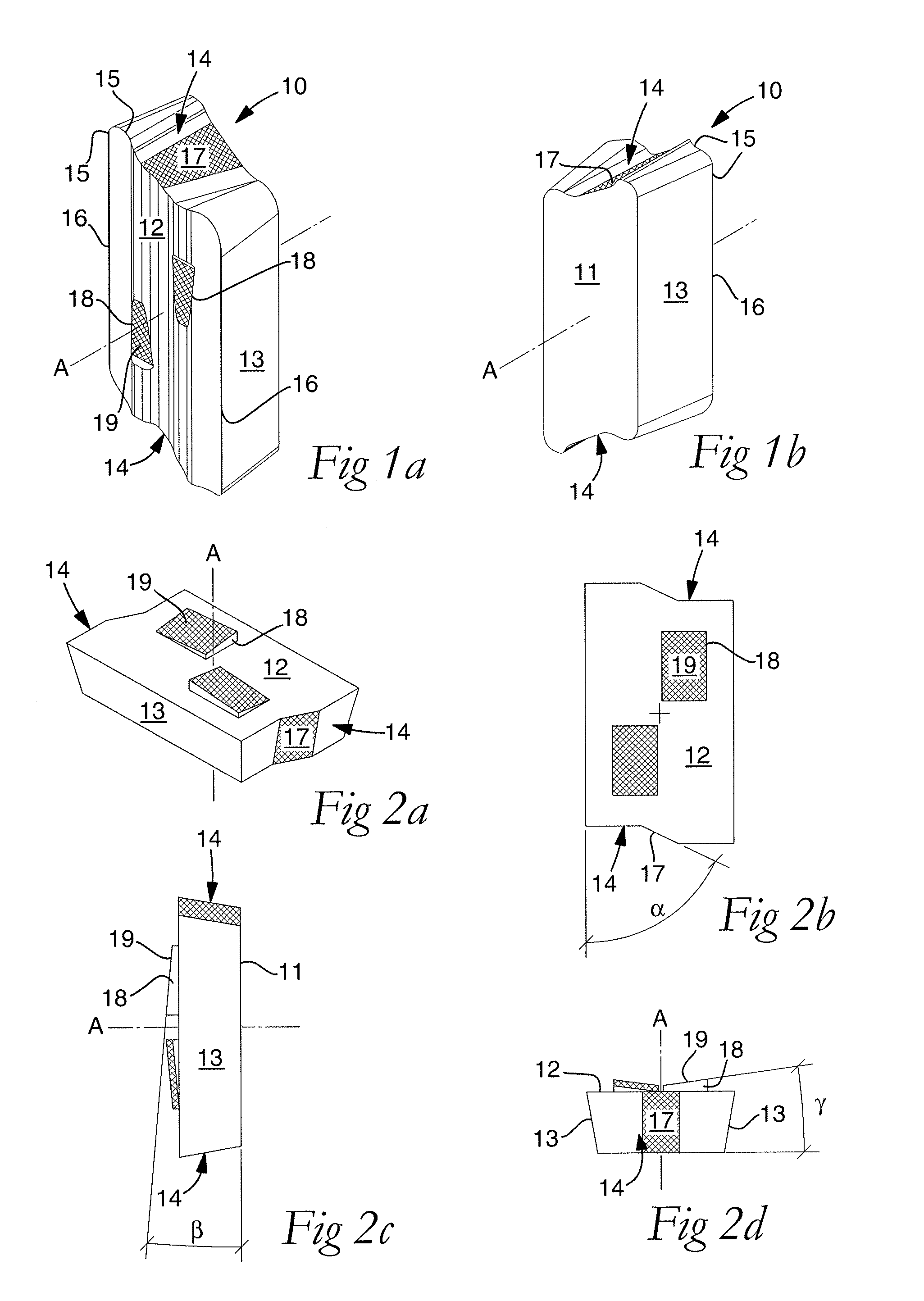
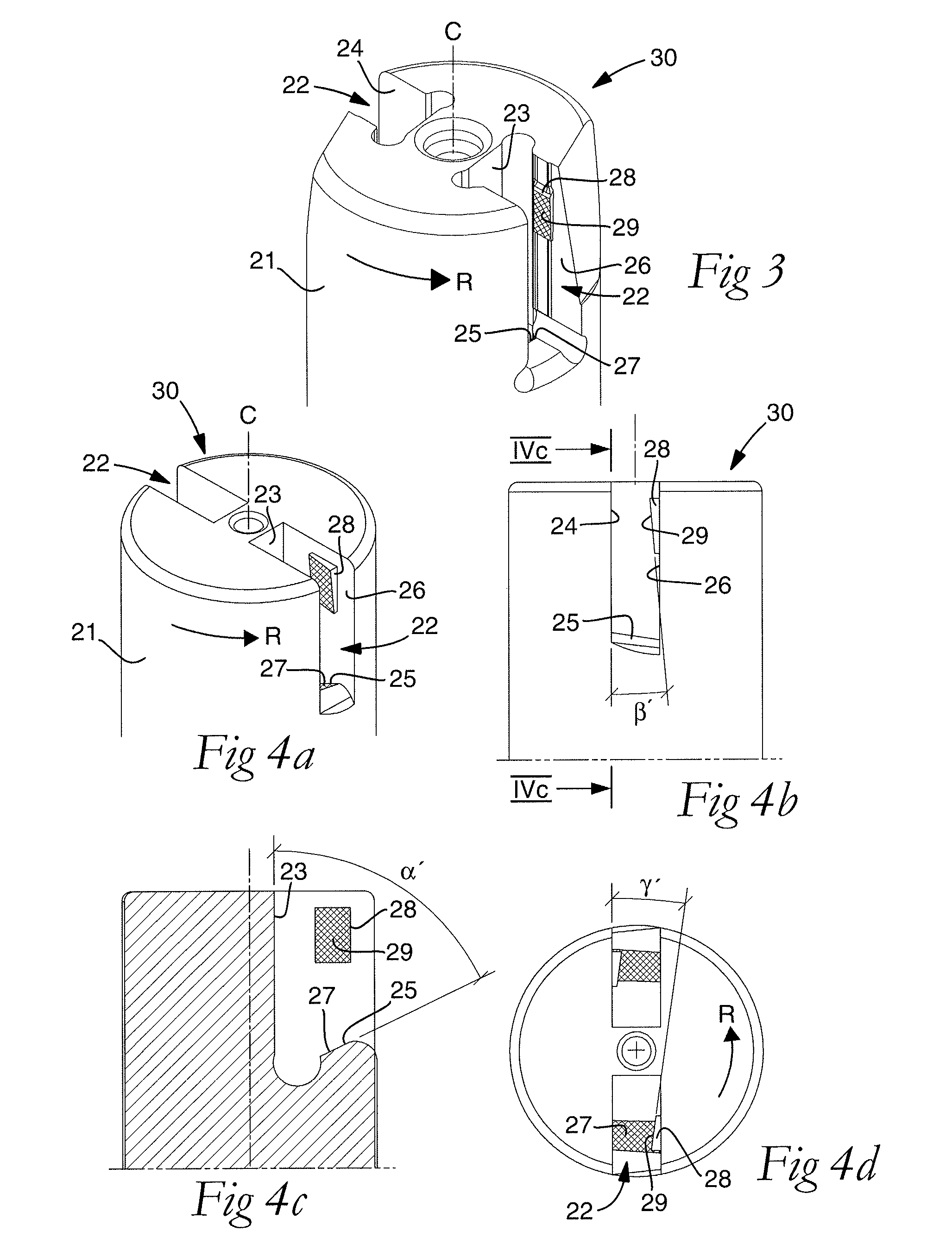
[0038]A design of the milling insert 10 according to an embodiment of the invention is shown in FIGS. 1a,b. The milling insert 10 includes a bottom surface 11 and an opposite chip surface 12 between which side surfaces extend. Two of the side surfaces are primary clearance surfaces 13 and two of the side surfaces are secondary clearance surfaces 14. The milling insert 10 has a plurality of cutting edges 15 formed between the chip surface 12 and the clearance surfaces 13, 14. Each one of the cutting edges 15 preferably includes a chip removing main cutting edge 16 and a surface-wiping minor cutting edge, e.g. a wiper edge adjacent to one of the corners. The main cutting edges 16 connect to the primary clearance surfaces 13 and are primarily parallel. However, the main cutting edges 16 do not necessarily need to be parallel in their entire length, but smaller deviations from the parallel design may occur. As seen from above, toward the chip surface 12, and as seen from below, toward t...


PUM

PropertyMeasurementUnit
angleaaaaaaaaaa
angleaaaaaaaaaa
angleaaaaaaaaaa

Abstract

An indexable milling insert for milling tools, including a bottom surface, an opposite chip surface, and a plurality of side surfaces extending between the bottom surface and the opposite chip surface, two of the side surfaces being primary clearance surfaces and two of the side surfaces being secondary clearance surfaces. A plurality of cutting edges are formed between the opposite chip surface and the primary and secondary clearance surfaces. Two of the cutting edges that connect to the primary clearance surfaces are primarily parallel and constitute main cutting edges. At least one lock structure is provided and includes a locking surface arranged on one of the secondary clearance surfaces so that the locking surface and the primary clearance surface form an acute angle, α, in a section that is parallel to the bottom surface and intersects the locking surface. A coupling structure is arranged on the opposite chip surface and at least partly projects from a plane that is parallel to the bottom surface and passes through points of the main cutting edges situated closest to the bottom surface. The coupling structure comprises at least one flank surface, which is arranged in such a way that the flank surface, in a section that is parallel to the primary clearance surface and intersects the flank surface, forms an acute angle, β, with the bottom surface so that the flank surface slopes in the direction from the secondary clearance surface on which the locking surface is arranged.

Description

[0001]This application claims priority under 35 U.S.C. §119 to Swedish Patent Application No. 1050459-5 filed on May 10, 2010, which is incorporated by reference herein in its entirety.FIELD OF THE INVENTION[0002]The present invention relates generally to an indexable milling insert and a corresponding basic body, intended for use in milling tools of small diameters, foremost in rotary shank-end mills for the machining of metallic workpieces. The invention also relates generally to a milling tool having indexable milling inserts detachably mounted in a basic body.BACKGROUND OF THE INVENTION[0003]Face milling is an efficient method for machining surfaces. One of the milling tools that can be used for face milling is the shank-end mill, which advantageously may be used for operations such as machining of shoulders, grooves and edges, and is constructed to give axial reach. By a greater axial reach, i.e., milling depth, more material can be removed in the same operation, which is econo...

Claims


Application Information

Patent Timeline
Patent Type & Authority Patents(United States)
IPC IPC(8): B23C5/20B23B27/16
CPCB23C5/109B23C5/202B23C5/2273B23C2200/081B23C2200/085Y10T407/2274B23C2200/286B23C2210/161B23C2210/168Y10T407/192Y10T407/23B23C2200/208B23C5/205B23C2200/287B23B51/00B23C5/20B23B51/0003B23C5/2298
Inventor KAKAI, ISAK
Owner SANDVIK INTELLECTUAL PROPERTY AB
Why Eureka
Eureka Blog
Learn More