Developing device and image forming apparatus

a technology of developing device and image forming apparatus, which is applied in the direction of electrographic process apparatus, instruments, optics, etc., can solve the problems of image degradation, image degradation, image degradation, etc., and achieve the effect of preventing image degradation

Active Publication Date: 2013-06-25
COPYER
View PDF4 Cites 1 Cited by
  • Summary
  • Abstract
  • Description
  • Claims
  • Application Information

AI Technical Summary

Benefits of technology

[0011]The present invention provides a developing device capable of performing balanced supply of a developer within a developer container irrespective of a change of an agglomeratability of the developer, to thereby prevent image degradation ascribable to unevenness in a longitudinal direction of a distribution of an amount of fall of the developer with which the developer container is replenished.
[0013]As described above, according to the aspect of the present invention, an upper surface of the upper rim portion is set wider as the upper rim portion of the developer regulating wall becomes lower, and hence the developer regulating wall is formed so that the developer stacked on the upper rim portion of the developer regulating wall has a higher height in a position in which the developer regulating wall is lower. A wall is formed by the developer transported within the developer transport path, and hence the developer is transported in the longitudinal direction while falling so as to climb over the wall of the developer itself. The wall formed by the developer has a lower height as the agglomeratability of the developer becomes lower and has a higher height as the agglomeratability becomes higher. That is, if an apparatus is subjected to a change in the use environment or the like to have the agglomeratability of the developer changed, the wall stacked on the upper surface of the upper rim portion of the developer regulating wall is changed in height. Even if the use environment becomes a high humidity environment and the agglomeratability of the developer becomes higher, the upper rim portion of the developer regulating wall becomes lower in height on the downstream side in the developer transport direction and the width of the surface of the upper rim portion on the downstream side in the developer transport direction becomes larger. Accordingly, a constant height of the wall of the developer formed on the developer regulating wall on the downstream side in the developer transport direction tends to be maintained, a constant amount of the supply of the developer is maintained, and which enables the distribution of the amount of fall of the developer falling into the developer container to be controlled evenly in the longitudinal direction. As a result, the balanced supply of the developer within the developer container to the developer carrying member is performed, and occurrence of image degradation ascribable to the distribution of the amount of fall in the longitudinal direction due to developer replenishment performed within the developer container in the longitudinal direction is prevented.
[0014]Further, according to another aspect of the present invention, with such a structure that a supply port for the developer is provided to the developer transport path in proximity to a position in which the upper rim portion of the developer regulating wall has a maximum height, the amount of fall can be controlled to become even by preventing the developer from climbing over the developer regulating wall when an enormous amount of developer is supplied from the supply port in a case where, for example, clogging of the developer within a hopper is eliminated. Accordingly, the balanced supply of the developer within the developer container to the developer carrying member is performed, and the occurrence of image degradation ascribable to the distribution of the amount of fall in the longitudinal direction due to the developer replenishment performed within the developer container in the longitudinal direction is prevented.
[0015]Further, according to further another aspect of the present invention, with such a structure that a helical-shaped screw is provided as the developer transporting unit provided with the developer transport path, transport of the developer within a transport route in the longitudinal direction is stabilized, and the amount of fall toward the developer carrying member can be controlled to become even. Accordingly, the balanced supply of the developer within the developer container to the developer carrying member is performed, and the occurrence of image degradation ascribable to the distribution of the amount of fall in the longitudinal direction due to the developer replenishment performed within the developer container in the longitudinal direction is prevented.
[0016]Further, according to still another aspect of the present invention, with such a structure that the developer is subjected to replenishment from a developer supply portion intermittently, transport of the developer within the transport route in the longitudinal direction is stabilized, and the amount of fall toward the developer carrying member can be controlled to become even. Accordingly, the balanced supply of the developer within the developer container to the developer carrying member is performed, and the occurrence of image degradation ascribable to the distribution of the amount of fall in the longitudinal direction due to the developer replenishment performed within the developer container in the longitudinal direction is prevented.
[0017]As described above, according to one aspect of the present invention, the upper rim portion of the developer regulating wall for regulating the amount of the developer falling from the developer transport path along the developer transport direction of the developer transport path is inclined so as to become lower in height toward the developer transport direction of the developer transport path, and the width of the surface of the upper rim portion in the direction orthogonal to the developer transport direction of the developer transport path is enlarged along the developer transport direction of the developer transport path to thereby form a wall by the developer transported in the developer transport path. Thus, the fall of the transported developer toward a direction orthogonal to the longitudinal direction is regulated by the wall of the developer itself. Hence, even if the agglomeratability of the developer changes due to environmental conditions, the wall of the developer stacked on the upper surface of the developer regulating wall changes in height, and the supply of the developer in the longitudinal direction and the fall thereof toward the direction orthogonal to the longitudinal direction are performed substantially evenly irrespective of the agglomeratability of the developer. Accordingly, the occurrence of image degradation ascribable to the distribution of the amount of fall in the longitudinal direction due to the developer replenishment performed within the developer container in the longitudinal direction is prevented, and reliability of the developing device and the image forming apparatus can be enhanced with a simple structure.

Problems solved by technology

However, when the developer having an excessively agglomeratability is supplied, the developer transported within the developer transport path 1 cannot climb over the developer regulating wall 3 in its high position, and a large amount of developer falls on a downstream side of the developer transport path 1 in the longitudinal direction.
In any one of the cases, the supply of the developer within the developer container toward the longitudinal direction becomes one-sided, which causes image degradation ascribable to unevenness of the distribution of the amount of fall of the developer.
This causes image degradation corresponding to the distribution of the amount of fall within an image.
Further, a phenomenon in which an extraneous substance adheres to the developer in advance occurs on a surface of the developer carrying member which is opposed to the position in which a larger amount of developer falls, which tends to cause image degradation.

Method used


Image

  • Developing device and image forming apparatus
  • Developing device and image forming apparatus
  • Developing device and image forming apparatus

Examples


Embodiment Construction

[0034]Hereinafter, an embodiment obtained by applying the present invention to a copying machine functioning as an image forming apparatus is described in detail with reference to the accompanying drawings.

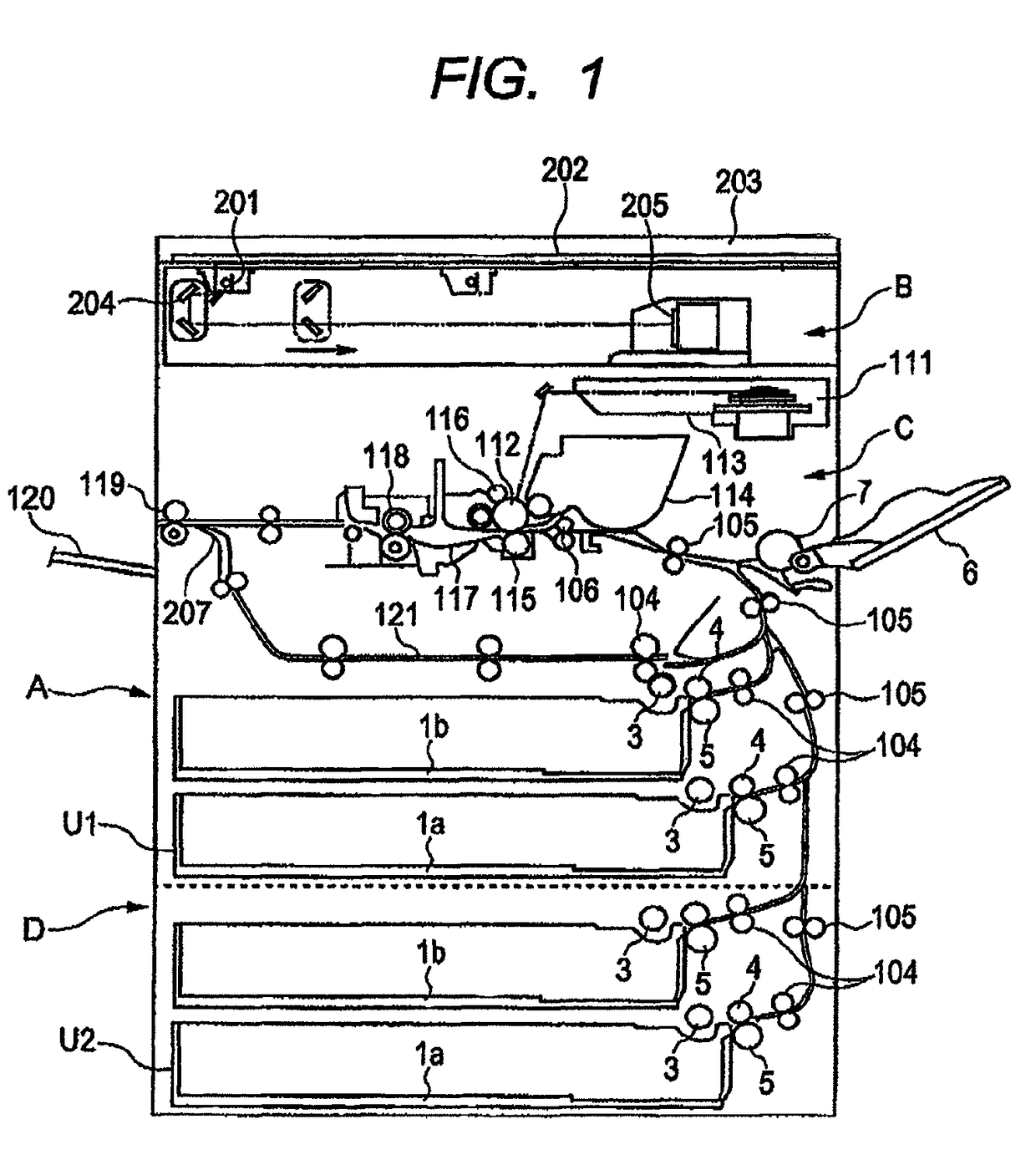
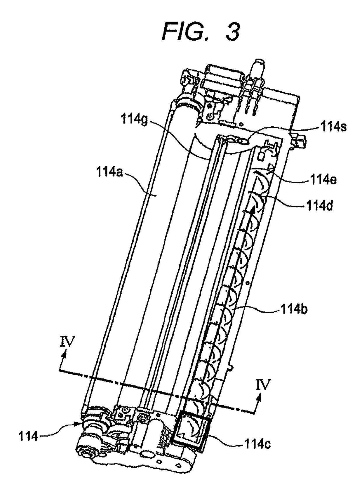
[0035]First, as illustrated in FIG. 1, an overall structure of the copying machine to which the present invention is applied includes a scanner section B, an image forming section C, and a sheet deck D which are provided as sections of an image forming apparatus main body A. The scanner section B functioning as a image reading unit for reading image information of a book original is located in an upper part of the above-mentioned image forming apparatus main body A, and the image forming section C functioning as a image forming unit is provided in a lower part of the image forming apparatus main body A. Further, the sheet deck D is assembled below the image forming section C. As illustrated in FIG. 3, a developing device 114 includes a developer container for containing a develope...


PUM


Abstract

Provided is a developing device capable of, with a simple structure, preventing occurrence of image degradation ascribable to a distribution of an amount of fall in a longitudinal direction due to developer replenishment within a developer container. An upper rim portion of a developer regulating wall for adjusting an amount of a developer falling along a developer transport direction of a developer transport path is inclined so as to become low in height in the developer transport direction of the developer transport path. A width of a surface in the developer transport direction of the developer transport path is enlarged along the developer transport direction of the developer transport path. A wall is formed by the developer transported on the developer transport path, and the developer transported in a longitudinal direction is transported in the longitudinal direction while breaking a wall of the developer itself.

Description

BACKGROUND OF THE INVENTION[0001]1. Field of the Invention[0002]The present invention relates to a developing device including a developer regulating wall for regulating an amount of developer falling along a transport direction of a developer transport path, and an image forming apparatus including the same.[0003]2. Description of the Related Art[0004]In recent years, the sizes of an electrophotographic copying machine, an information recording apparatus, and the like are getting smaller and smaller. With the trend toward a downsized developing device and a smaller developer containing capacity so that multiple developing devices can be provided within a limited space around an electrostatic latent image bearing member, it is becoming common practice to separately provide a developer supply portion (hereinafter, referred to as “hopper”). In this case, the supply of the developer from the hopper to the developing device is ideally performed evenly throughout an axial direction of a ...

Claims


Application Information

Patent Timeline
Patent Type & Authority Patents(United States)
IPC IPC(8): G03G15/08
CPCG03G15/0822G03G2215/0802G03G2215/0822
Inventor KAYAHARA, YASUFUMI
Owner COPYER
Why Eureka
Try Eureka