
Liquid ejection using drop charge and mass

a technology of charge and mass, applied in the direction of printing, etc., can solve the problems of charging electrodes shifting and warping with temperature, limiting the fundamental nozzle spacing and therefore the resolution of the printing system, and the droplet generator and the associated stimulation device may not be perfectly uniform down the nozzle array, so as to reduce the variation of the drop volume and the drop placement accuracy. , the effect of high resolution and high quality

Active Publication Date: 2013-06-18
EASTMAN KODAK CO
View PDF29 Cites 10 Cited by
  • Summary
  • Abstract
  • Description
  • Claims
  • Application Information

AI Technical Summary

Benefits of technology

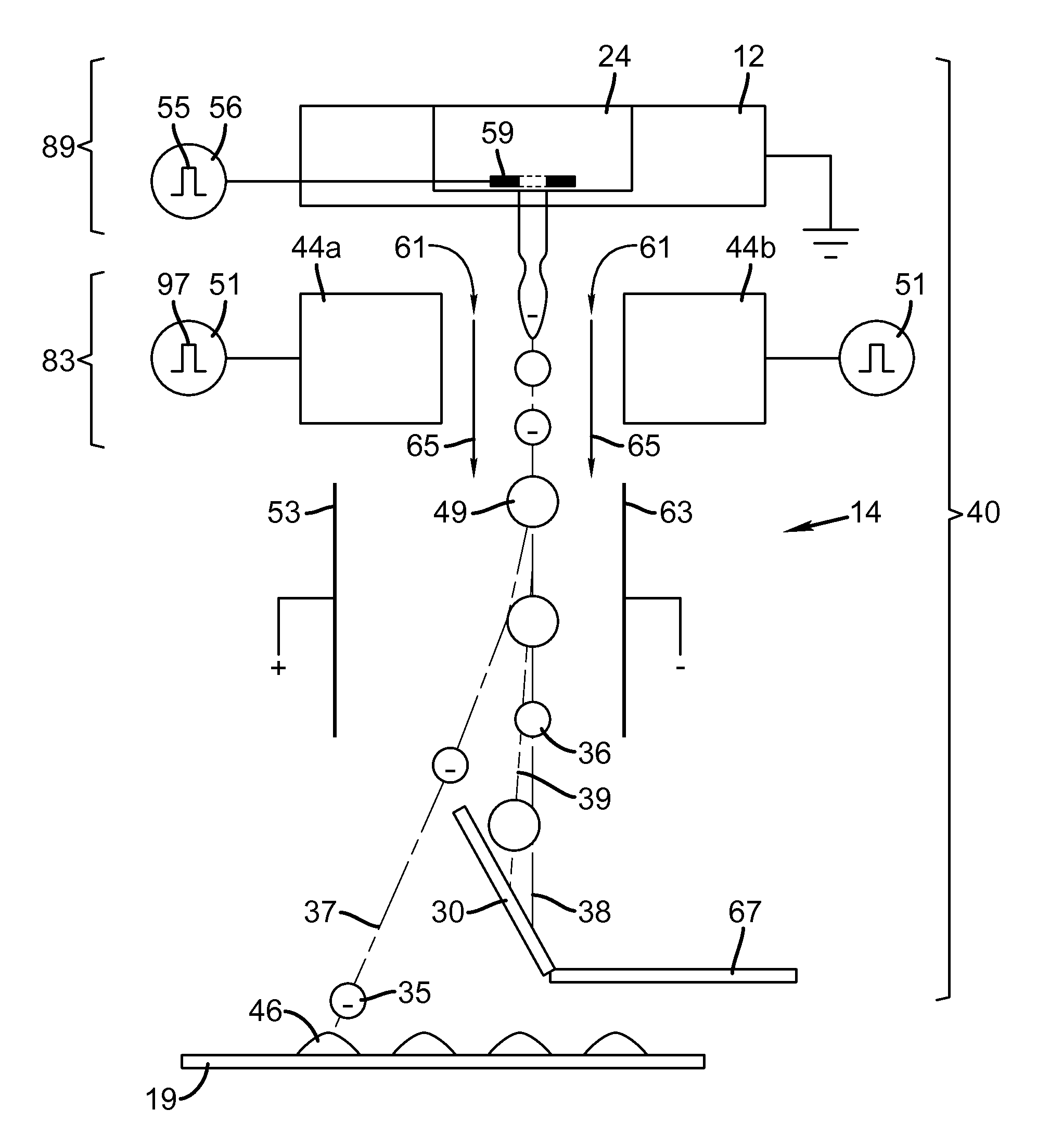
[0011]It is an object of the invention to overcome at least one of the deficiencies described above by using mass charging and electrostatic deflection with a CMOS-MEMS printhead to create high resolution high quality prints while maintaining or improving drop placement accuracy and minimizing drop volume variation of printed drops.
[0013]The present invention helps to provide system robustness by allowing larger tolerances on break-off time variations between jets in a long nozzle array. Additionally, at least every other drop is collected by a catcher helping to ensure that liquid remains on the catcher which reduces the likelihood of liquid splatter during operation. The present invention reduces the complexity of control of signals sent to stimulation devices associated with nozzles of the nozzle array. This helps to reduce the complexity of charge electrode structures and increase spacing between the charge electrode structures and the nozzles.

Problems solved by technology

This requirement for individually addressable charge electrodes places limits on the fundamental nozzle spacing and therefore on the resolution of the printing system.
However, in a printhead having an array of nozzles parts tolerances can make this quite difficult.
In addition, the droplet generator and the associated stimulation devices may not be perfectly uniform down the nozzle array, and may require different stimulation amplitudes from nozzle to nozzle to produce particular break off lengths.
These problems are compounded by ink properties that drift over time, and thermal expansion that can cause the charging electrodes to shift and warp with temperature.
One of the disadvantages of this approach is that deflected drops are printed which could result in drop placement errors.
This limits the density of nozzle spacing that can be utilized in such an approach and severely limits the capability to print high resolution images.

Method used


Image

  • Liquid ejection using drop charge and mass
  • Liquid ejection using drop charge and mass
  • Liquid ejection using drop charge and mass

Examples


Embodiment Construction

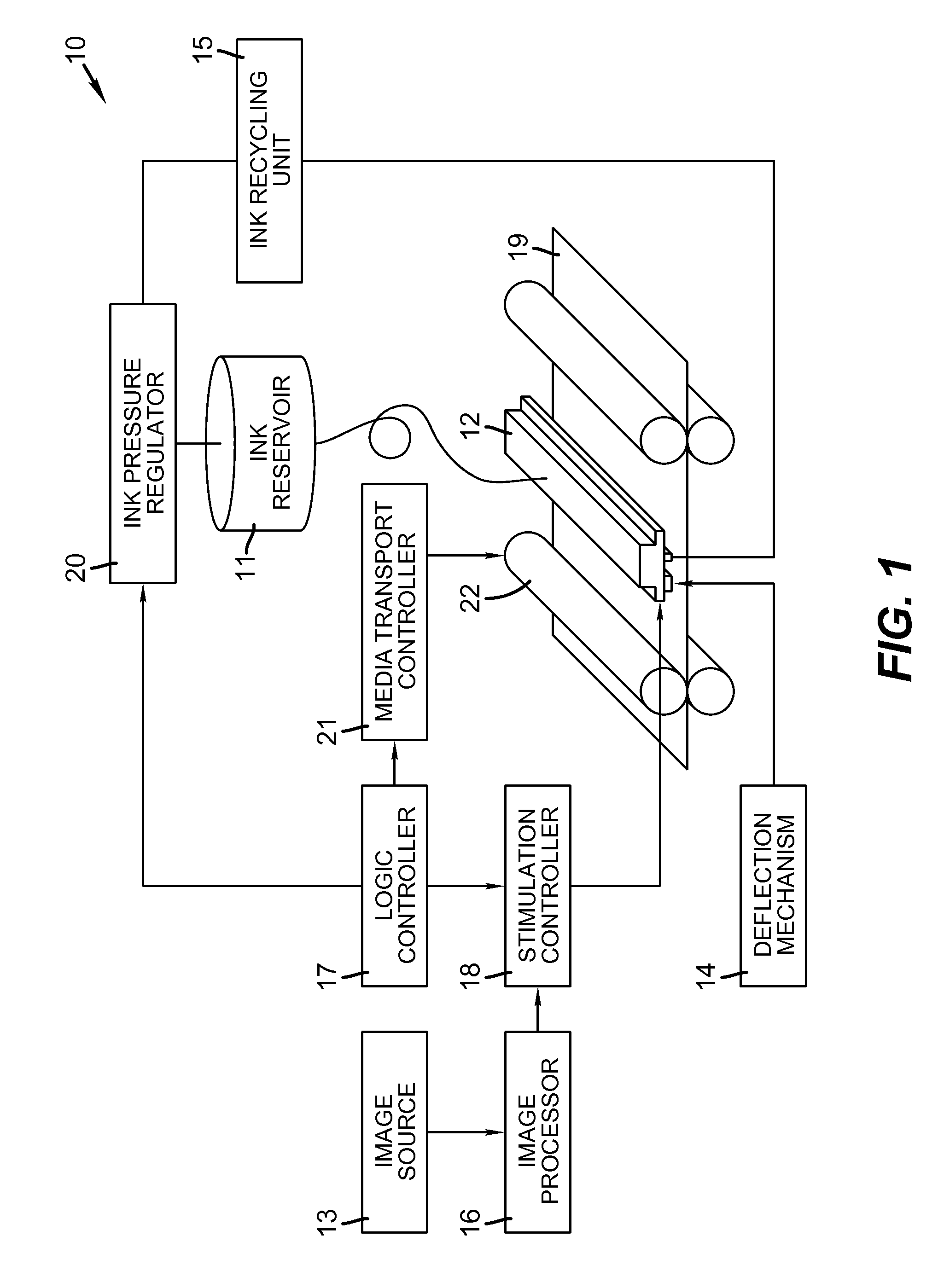
[0033]The present description will be directed in particular to elements forming part of, or cooperating more directly with, apparatus in accordance with the present invention. It is to be understood that elements not specifically shown or described may take various forms well known to those skilled in the art. In the following description and drawings, identical reference numerals have been used, where possible, to designate identical elements.

[0034]The example embodiments of the present invention are illustrated schematically and not to scale for the sake of clarity. One of the ordinary skills in the art will be able to readily determine the specific size and interconnections of the elements of the example embodiments of the present invention.

[0035]As described herein, example embodiments of the present invention provide a printhead or printhead components typically used in inkjet printing systems. In such systems, the liquid is an ink for printing on a recording media. However, o...


PUM


Abstract

A liquid ejection system ejects a liquid jet through a nozzle. A drop formation device modulates the jet causing portions to break off into drop pairs, including first and second drops, separated on average by a drop pair period, and modulates the jet to cause portions to break off into larger third drops separated on average by the same period. A charging device includes a varying electrical potential source providing a waveform including first and second distinct voltage states and a period equal to the drop formation period. The charging device and the formation device are synchronized to produce first, second, and third charge to mass ratios on the first, second, and third drops, respectively. A deflection device causes the first, second, and third drops to travel along first, second, and third paths, respectively. The first and third charge to mass ratios and paths are substantially the same.

Description

CROSS REFERENCE TO RELATED APPLICATIONS[0001]Reference is made to commonly-assigned, U.S. patent application Ser. No. 13 / 115,434, entitled “EJECTING LIQUID USING DROP CHARGE AND MASS” filed concurrently herewith.FIELD OF THE INVENTION[0002]This invention relates generally to the field of digitally controlled printing systems, and in particular to continuous printing systems in which a liquid stream breaks into drops some of which are electrostatically deflected.BACKGROUND OF THE INVENTION[0003]Ink jet printing has become recognized as a prominent contender in the digitally controlled, electronic printing arena because, e.g., of its non-impact, low-noise characteristics, its use of plain paper and its avoidance of toner transfer and fixing. Ink jet printing mechanisms can be categorized by technology as either drop on demand ink jet (DOD) or continuous ink jet (CIJ).[0004]The first technology, “drop-on-demand” ink jet printing, provides ink drops that impact upon a recording surface ...

Claims


Application Information

Patent Timeline
Patent Type & Authority Patents(United States)
IPC IPC(8): B41J2/085
CPCB41J2/085
Inventor PANCHAWAGH, HRISHIKESH V.MARCUS, MICHAEL A.KATERBERG, JAMES A.
Owner EASTMAN KODAK CO
Learn More