Method and apparatus for concealing lost frame
a frame and frame technology, applied in the field of telecommunications, can solve the problems of data packet loss, inability to be completely reliable, and the network based on packet switching technology is not initially designed, and achieve the effect of improving qos
- Summary
- Abstract
- Description
- Claims
- Application Information
AI Technical Summary
Benefits of technology
Problems solved by technology
Method used
Image
Examples
embodiment 1
[0065]Only one MDCT coefficient after the lost frame is used to correct the first synthesized signal:
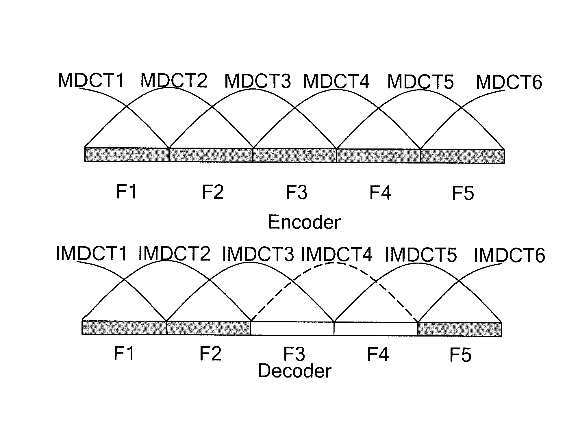
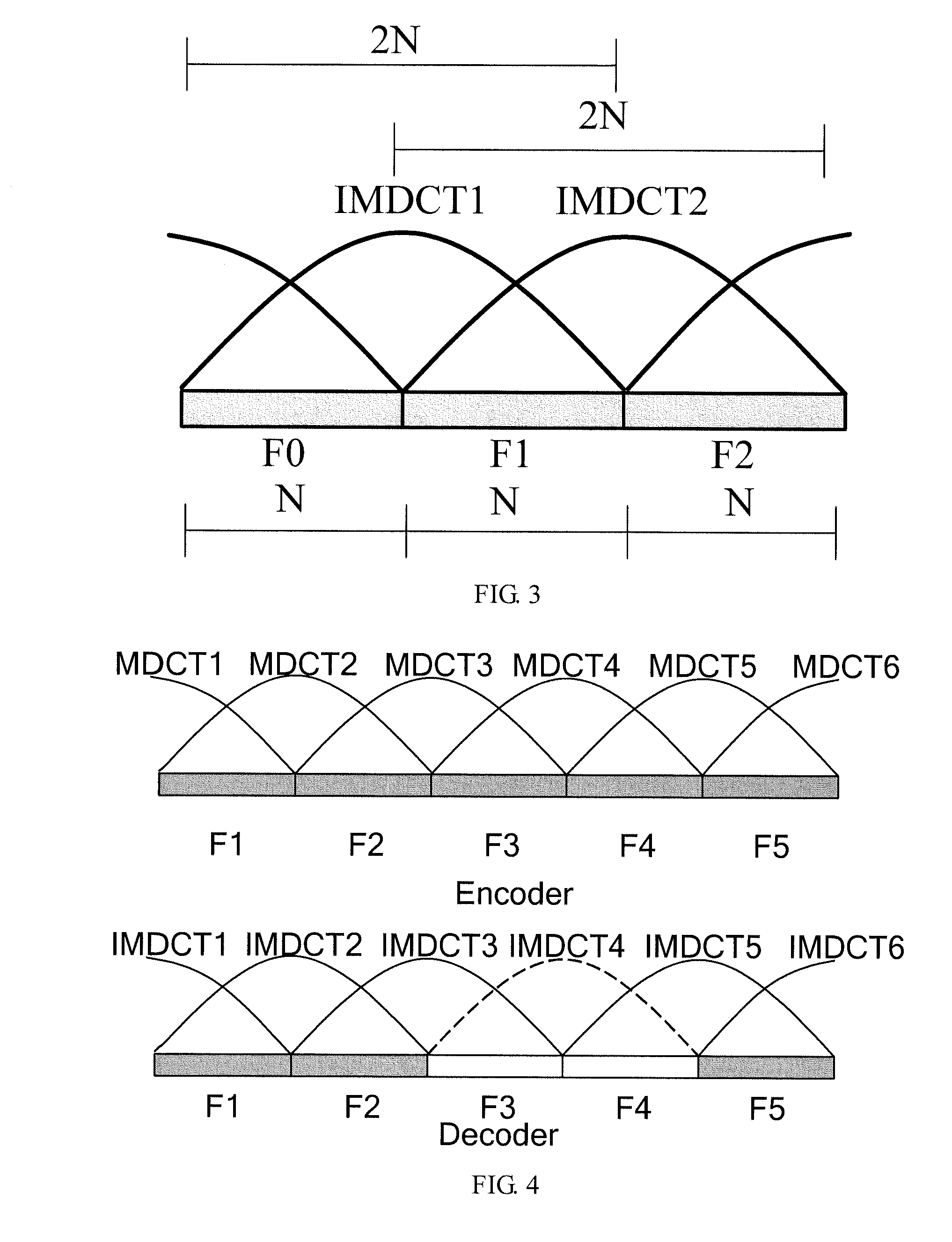
[0066]First, signals x′[n], n=0, . . . , 3N−1 corresponding to frame F3, frame F4, and frame F5 are synthesized according to block S1 shown in FIG. 6, and then x′[n] is performed phase synchronization, as shown in FIG. 8. Only one MDCT coefficient is available, and the signal corresponding to the IMDCT coefficient is an impaired signal in contrast to the original signal. However, according to the features of a windowed function, a finite number of samples near the joint of frame F4 and frame F5 have amplitude that is approximate to that of the original signal. Therefore, the finite number of samples may be used to perform phase synchronization for the synthesized signal, as detailed below:
[0067]The start sample of the IMDCT coefficient corresponding to frame F5 is regarded as a midpoint, Mfp samples before the midpoint and Mfp samples after the midpoint are used as fixed template win...
embodiment 2
[0076]Multiple continuous MDCT coefficients after the lost frame are used to correct the first synthesized signal:
[0077]2.1 Only Phase Synchronization is Performed.
[0078]Taking FIG. 9 as an example, this method is elaborated below. It is assumed that z[n], n=0, . . . , L−1 are complete signals after the lost frame, and L is the number of complete samples available after the lost frame. As shown in FIG. 9, z[n], n=0, . . . , L−1 correspond to frame F5 and frames after F5.
[0079]First, the signals x′[n], n=0, . . . , 3N−1 corresponding to frames F3, F4, and F5 are synthesized according to block S1 in FIG. 6. Afterward, z[n] is used to perform phase matching for x′[n] and the corresponding phase difference dbp is obtained. Specifically, The begin Mbp length of z[n] is regarded as a signal template, and then the phase difference dbp is obtained near the sample point x′[2N] in x′[n] according to formula (14):
[0080]dbp=arg(min(∑j=0Mbp-1x′[2N+j+i]-z[j]))i=-Rbp,…,Rbp(14)
[0081]Wherei...
PUM
 Abstract
Description
Claims
Application Information
 - R&D
- Intellectual Property
- Life Sciences
- Materials
- Tech Scout
- Unparalleled Data Quality
- Higher Quality Content
- 60% Fewer Hallucinations
Browse by: Latest US Patents, China's latest patents, Technical Efficacy Thesaurus, Application Domain, Technology Topic, Popular Technical Reports.
© 2025 PatSnap. All rights reserved.Legal|Privacy policy|Modern Slavery Act Transparency Statement|Sitemap|About US| Contact US: help@patsnap.com


