
Light bar proximity switch

a proximity switch and light bar technology, applied in the field of proximity switches, can solve the problem that labels can be worn off throughout the use of switches

Active Publication Date: 2013-06-04
FORD GLOBAL TECH LLC
View PDF105 Cites 39 Cited by
  • Summary
  • Abstract
  • Description
  • Claims
  • Application Information

AI Technical Summary

Benefits of technology

The present invention aims to provide an improved technology for certain applications. The technical effects of this invention include improved efficiency, reliability, and / or performance. These effects can benefit a wide range of industries and applications.

Problems solved by technology

Such switches can be labeled by laser etching or pad printing, which typically requires an additional manufacturing step, and such labels can be worn off throughout use of the switch.

Method used


Image

  • Light bar proximity switch
  • Light bar proximity switch
  • Light bar proximity switch

Examples


Embodiment Construction

[0014]As required, detailed embodiments of the present invention are disclosed herein; however, it is to be understood that the disclosed embodiments are merely exemplary of the invention that may be embodied in various and alternative forms. The figures are not necessarily to a detailed design; some schematics may be exaggerated or minimized to show function overview. Therefore, specific structural and functional details disclosed herein are not to be interpreted as limiting, but merely as a representative basis for teaching one skilled in the art to variously employ the present invention.

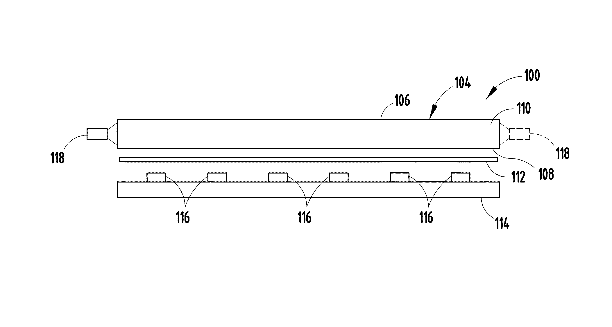
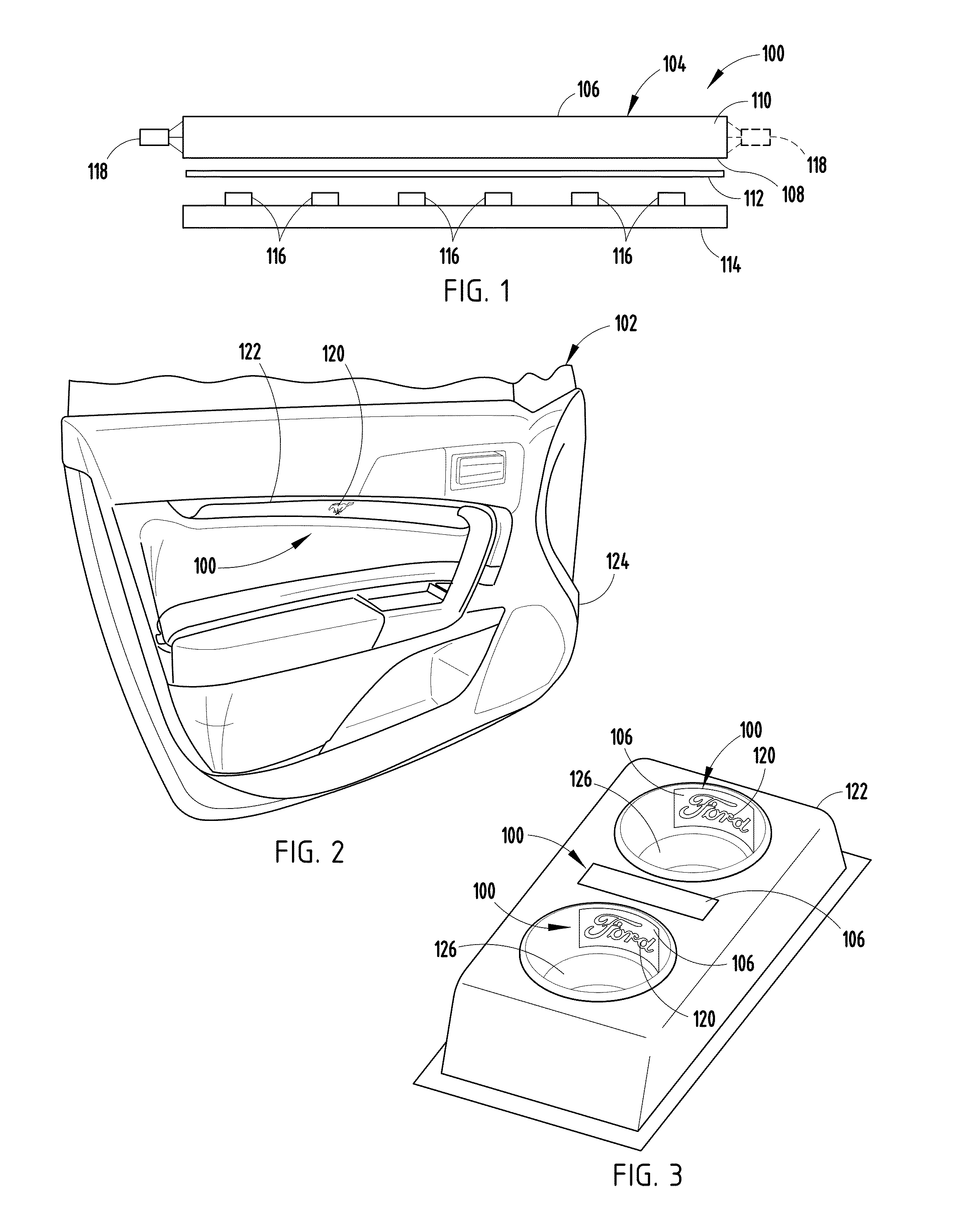
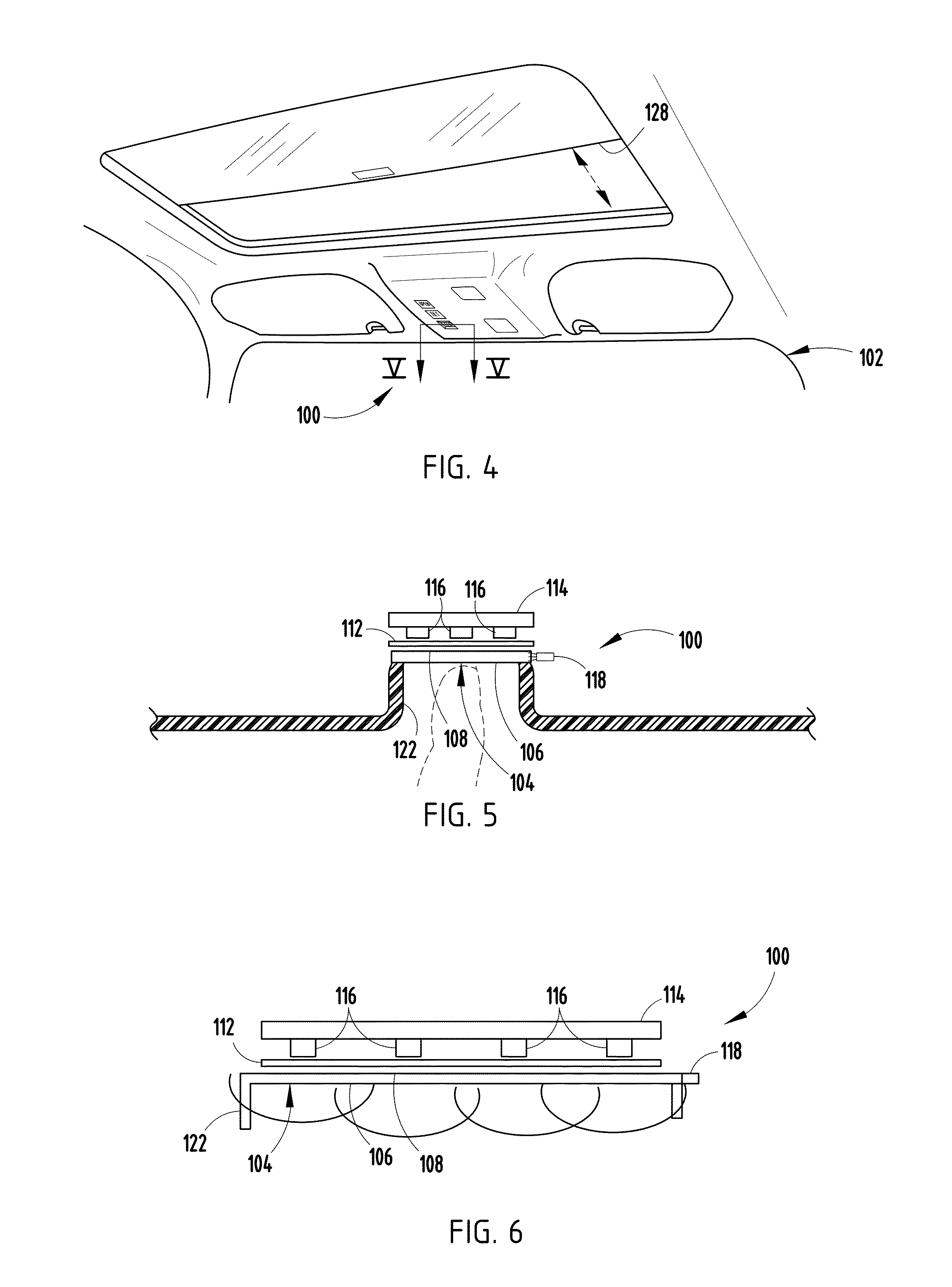
[0015]With respect to FIGS. 1-6, a light bar proximity switch is generally shown at reference identifier 100. Typically, the light bar proximity switch 100 can be configured to operate a component of a vehicle, which is generally indicated at reference identifier 102 (FIGS. 2 and 4). The light bar proximity switch 100 can include a light pipe, generally indicated at reference identifier 104, where...


PUM


Abstract

A light bar proximity switch is provided that includes a light pipe having a first surface and a second surface, wherein the first and second surface define an area. The light bar proximity sensor further includes an at least partially reflective surface adjacent the second surface, at least one circuit board spaced from the light pipe and the at least partially reflective surface, at least one proximity sensor electrically connected to the at least one circuit board, and at least one light source configured to project light along the area, wherein the emitted light is reflected by the at least partially reflective surface and viewed through the first surface.

Description

FIELD OF THE INVENTION[0001]The present invention generally relates to a proximity switch, and more particularly, a light bar proximity switch.BACKGROUND OF THE INVENTION[0002]Typically, various vehicle components require switches, such as, switches for operating windows, headlights, windshield wipers, moon roofs, and radios. Generally, these types of switches need to be actuated in order to activate or deactivate the device or perform another type of control function. Thus, the switches themselves clearly indicate the type of actuation that is needed to create such a control signal. Such switches can be labeled by laser etching or pad printing, which typically requires an additional manufacturing step, and such labels can be worn off throughout use of the switch.SUMMARY OF THE INVENTION[0003]Accordingly, in a first disclosed embodiment, a light bar proximity switch is provided that includes a light pipe having a first surface and a second surface, wherein the first and second surfa...

Claims


Application Information

Patent Timeline
Patent Type & Authority Patents(United States)
IPC IPC(8): G01D13/20G01D13/02
CPCB60Q3/0296H03K17/96H03K17/9622H03K2217/96066H03K2217/96079B60Q3/82B60Q3/229
Inventor SALTER, STUART C.IGOE, DENIS PATRICKSINGER, JEFFREYGARDNER, CORNEL LEWIS
Owner FORD GLOBAL TECH LLC
Learn More