Liquid ejection device
a technology of liquid ejection and nozzle, which is applied in printing and other directions, can solve the problems of long maintenance treatment time, inability to clean and the nozzle face of the liquid ejecting head and the internal wall surface of the cap member
- Summary
- Abstract
- Description
- Claims
- Application Information
AI Technical Summary
Benefits of technology
Problems solved by technology
Method used
Image
Examples
first embodiment
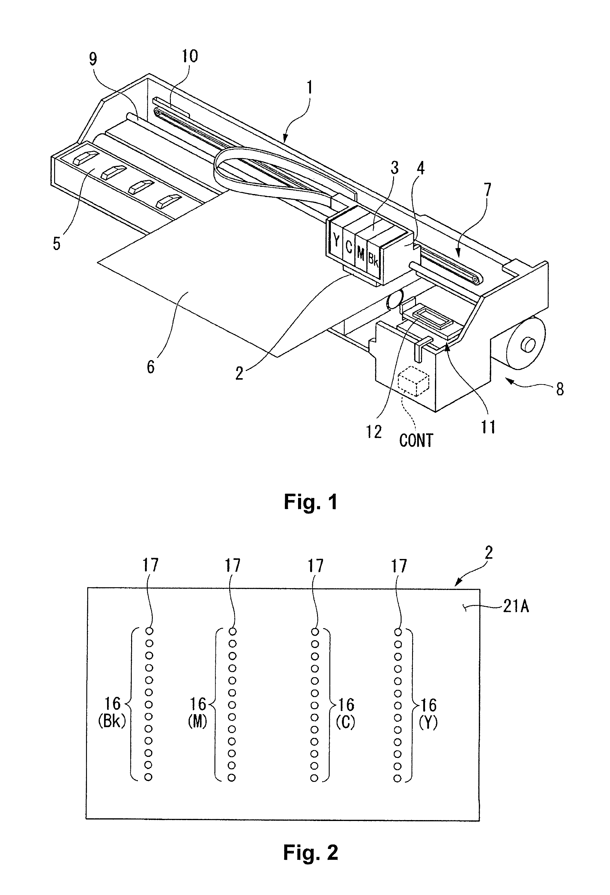
[0028]FIG. 1 is a perspective view showing constituent features of a printer 1 according to a first embodiment of the present invention.
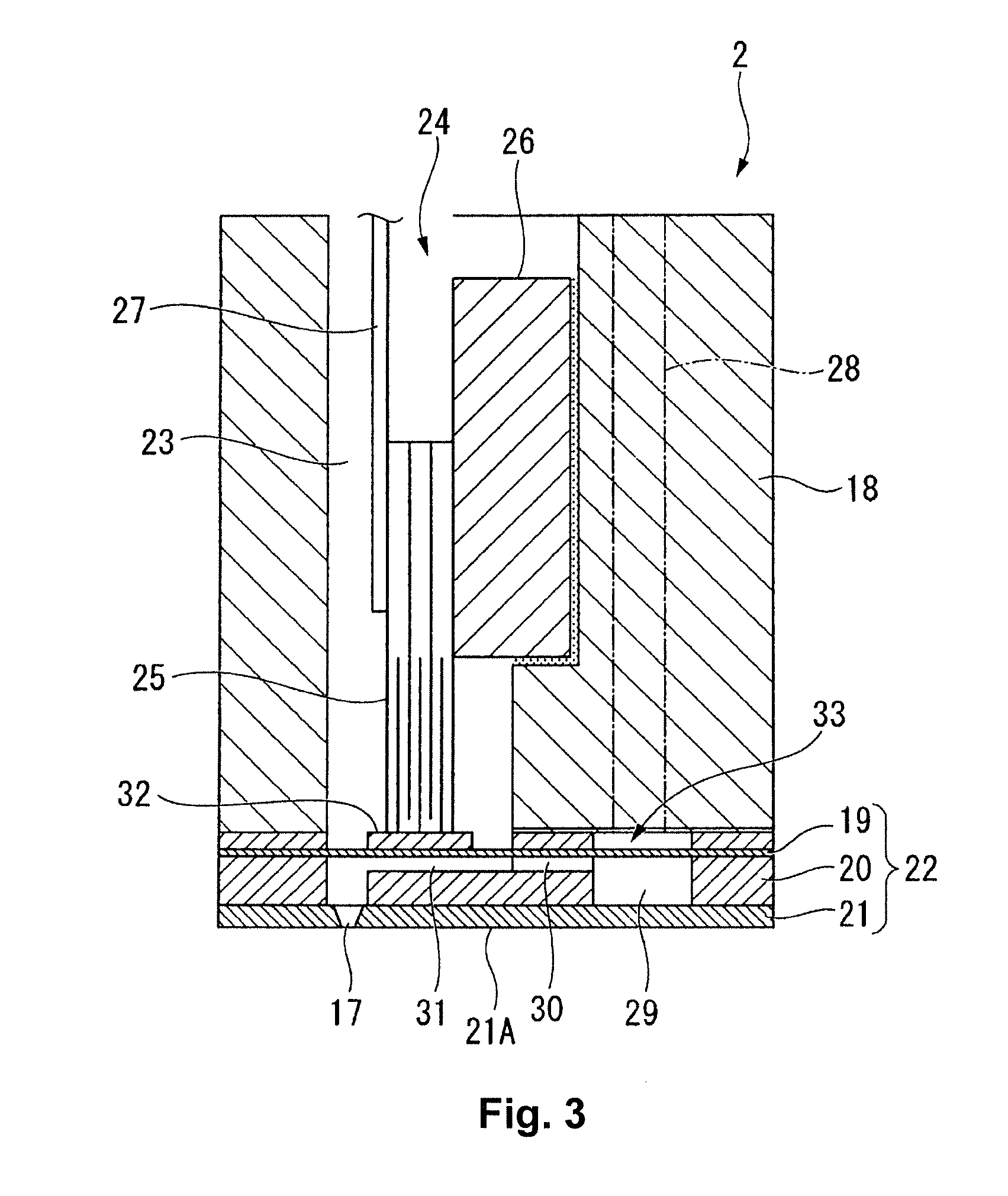
[0029]As shown in the same figure, the printer 1 includes a carriage 4 on which a recording head 2 exemplifying a type of liquid ejecting head is installed and an ink cartridge 3 is detachably mounted, a platen 5 arranged below the recording head 2 and serving to carry a recording paper 6, a carriage moving mechanism 7 configured to move the carriage 4 in a widthwise direction of the recording paper 6, and a paper feeding mechanism 8 configured to transport the recording paper 6 in a paper feed direction. Additionally, the printer 1 has a control device CONT configured to control the operations of the entire printer 1. The aforementioned widthwise direction of the paper is a main scanning direction (a head scanning direction). The aforementioned paper feed direction is a subordinate scanning direction (a direction perpendicular to the main scanning ...
second embodiment
[0063]FIG. 7 is a perspective view showing constituent features of a printer 101 according to a second embodiment of the present invention.
[0064]The printer 101 of the second embodiment differs from the printer 1 of the first embodiment in that a flow passage leading from the cap member 12 to the waste tank 103 and a flow passage leading from the cleaning liquid tank 14 to the cap member 12 are provided separately. Parts of the second embodiment that are the same as the parts of the printer 1 of the first embodiment are indicated with the same reference numerals and explanations thereof are omitted for the sake of brevity.
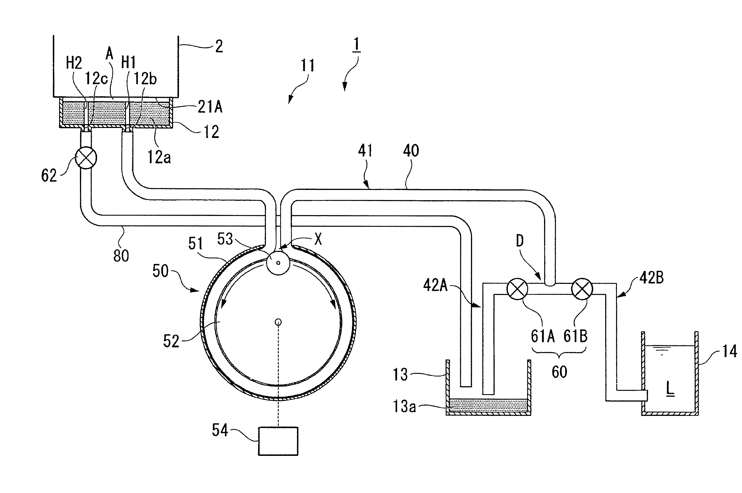
[0065]The capping mechanism 11 comprises a cap member 12, a waste liquid tank 13, a cleaning liquid tank 14, a waste liquid flow passage 73, a waste liquid pump (suction device) 71, a cleaning liquid flow passage 74, and a cleaning liquid pump 72.
[0066]The cap member 12 is has a bottomed cylinder-like form that is generally cup-like and open on a side facing the no...
PUM
 Abstract
Description
Claims
Application Information
 - R&D
- Intellectual Property
- Life Sciences
- Materials
- Tech Scout
- Unparalleled Data Quality
- Higher Quality Content
- 60% Fewer Hallucinations
Browse by: Latest US Patents, China's latest patents, Technical Efficacy Thesaurus, Application Domain, Technology Topic, Popular Technical Reports.
© 2025 PatSnap. All rights reserved.Legal|Privacy policy|Modern Slavery Act Transparency Statement|Sitemap|About US| Contact US: help@patsnap.com


