
Golf glasses

a technology for golf glasses and glasses, applied in golf clubs, golfing accessories, instruments, etc., can solve problems such as interference with the measurement of the distance to the ball

Active Publication Date: 2013-05-28
PARIS MIKI HLDG
View PDF12 Cites 9 Cited by
  • Summary
  • Abstract
  • Description
  • Claims
  • Application Information

AI Technical Summary

Benefits of technology

[0009]In consideration of the problems noted above, the present invention is intended to provide golf glasses to assist golfer's swing, particularly to enable the golfer to measure the distance to the ball precisely as taking the address position, and to keep golfer's head still and make looking at the ball until a clubhead hits the ball, in other words to prevent the golfer from looking-up movement during the swing.
[0021]As described above, the golf glasses of the present invention provide the golfer with limited horizontal view since each of the lenses of the glasses includes the see-through section formed of the vertical gap corresponding to the pupil of golfer's eye, and the other section designed to shade golfer's field of view, therefore makes the golfer aware of making looking-up mistake because the ball would be go out from his or her sight if he or she would lift head up during the swing, and thereby the golfer enables to prevent from looking-up movement.
[0022]In addition, the golf glasses of the present invention allow the golfer to overlook field of view from feet to the ball within a sight, and therefore enable the golfer to measure the distance from his or her body to the ball easily since the see-through section is formed of a vertical gap as described previously.

Problems solved by technology

However, a beginner golfer often makes a mistake to look up toward target point too early with lifting his or her head up during the swing before impact with the ball, which is called “look-up” or “head-up” mistake.
Taken into consideration that a golfer generally measures a distance to a golf ball with looking his or her feet and the ball within a sight at address, there remain some problems to be solved while these prior arts works well, since their see-through gaps limiting golfer's viewing field are formed of a circle or a horizontally long shape, therefore they would blind his or her feet when the golfer takes the address position, furthermore interfere with measuring the distance to the ball.

Method used


Image

  • Golf glasses
  • Golf glasses
  • Golf glasses

Examples


Embodiment Construction

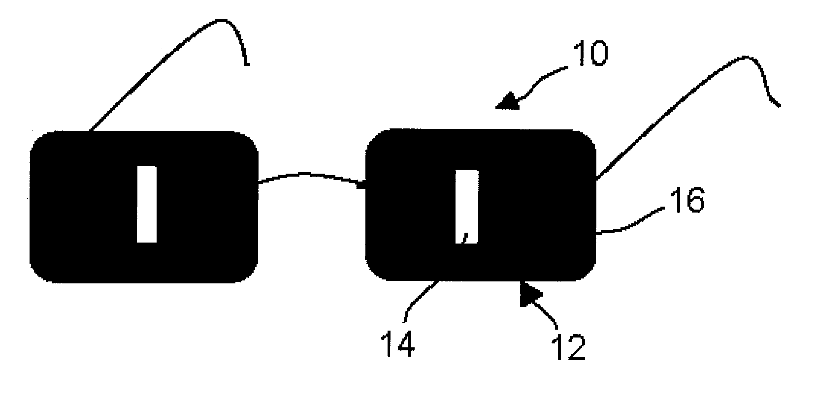
[0027]FIG. 1 represents golf glasses 10, illustrating an embodiment of the present invention in a schematic perspective view.

[0028]The golf glasses 10 are worn by a golfer in golf training or other occasions and keep golfer's head still and prevent the golfer from looking-up movement during a golf swing.

[0029]As shown in FIG. 1, in the golf glasses 10, a part of each of the lenses of the glasses corresponding to the pupil of the golfer's eye is a see-through section 14 which is vertically long, and the other part is a view shielding section 16.

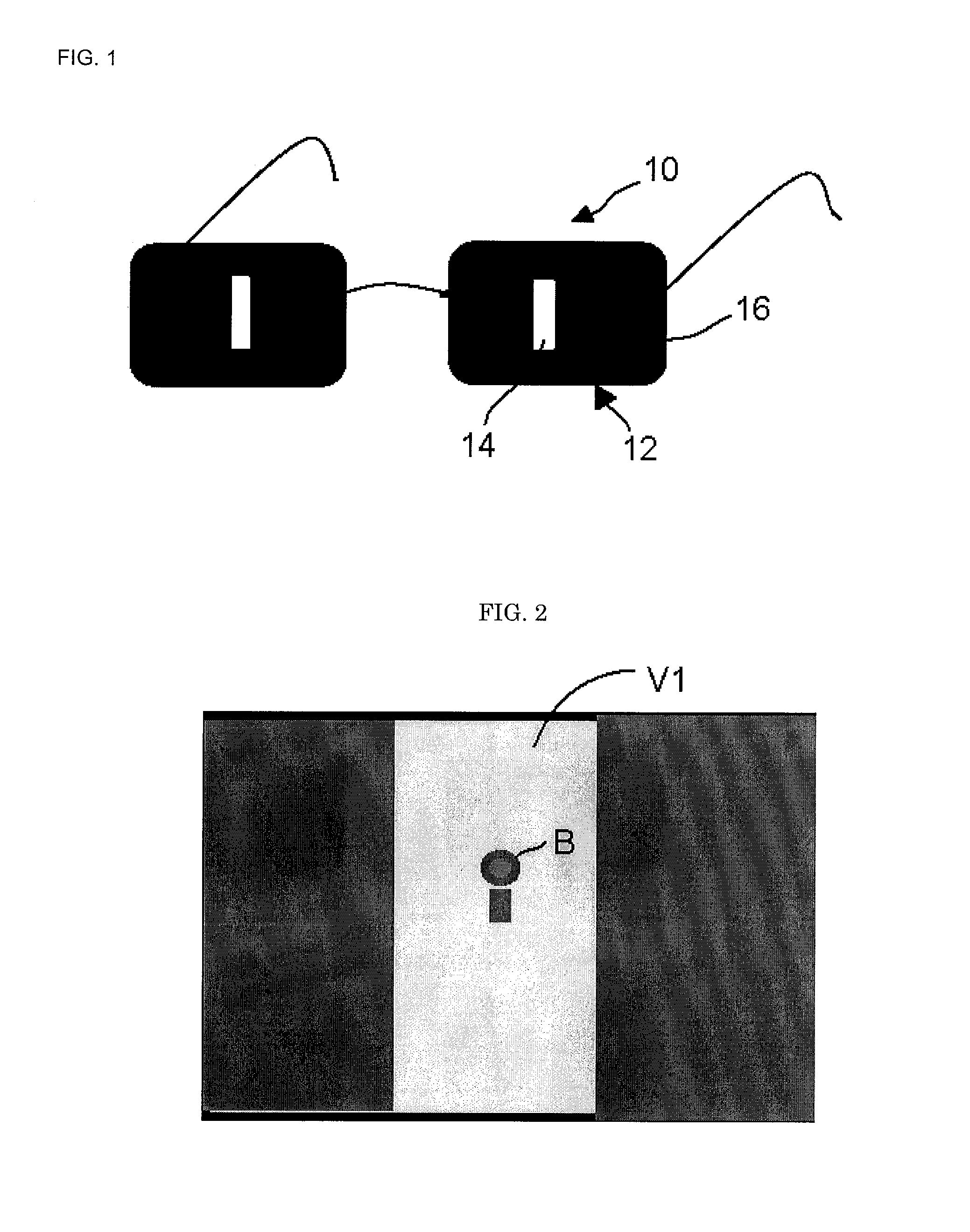
[0030]Since the width of the see-through section 14 of the lens is narrowed, the horizontally angular range of the golfer's view V1 is limited. Therefore, when the golfer looks at ball B through the see-through section 14 as shown in FIG. 2, the golf glasses 10 prevent the golfer from looking-up movement because if the golfer lifts his or her head up only slightly, the golfer would not look at ball B within the field of view.

[0031]On the contr...


PUM


Abstract

The present invention relates to a pair of golf glasses. The glasses are designed to enable the golfer to measure a distance to a golf ball precisely as taking an address position, and make the golfer looking at a ball with keeping his or her head still until a clubhead hits the ball, and thereby prevent the golfer from looking-up mistake during a golf swing. The golf glasses of the present invention are characterized in that each of the lenses of the glasses includes a see-through section formed of a vertical gap corresponding to the pupil of golfer's eye, and the other part is a view shielding.

Description

BACKGROUND OF THE INVENTION[0001]1. Field of the Invention[0002]The present invention relates to golf glasses, more specifically golf glasses worn by a golfer and designed to prevent a golfer from looking-up movement during a golf swing.[0003]2. Background Art[0004]It is often described that, in order to swing smoothly and hit a golf ball right, a golfer should take a swing with his or her eyes on the ball from first to last, in other words with keeping his or her head still during a swing motion, so as to make both body and shoulders smoothly rotate in a unified manner.[0005]However, a beginner golfer often makes a mistake to look up toward target point too early with lifting his or her head up during the swing before impact with the ball, which is called “look-up” or “head-up” mistake.[0006]On this matter, conventionally, in order to make a golfer to look only at a ball surely and prevent from looking-up movement before impact, JP Utility Model Publication No. Sho62-160982 and JP ...

Claims


Application Information

Patent Timeline
Patent Type & Authority Patents(United States)
IPC IPC(8): A63B69/36G02C7/16G02C7/02G02C9/00
CPCA63B69/3608A63B69/3623G02C5/003G02C7/16A63B2209/10A63B2225/12A63B57/00G02C11/00
Inventor KAYAMA, YUJI
Owner PARIS MIKI HLDG
Learn More