Liquid ejecting apparatus and liquid charging method

a technology of liquid ejecting apparatus and liquid charging method, which is applied in the direction of printing, other printing apparatus, etc., can solve the problems of unnecessarily dumping of ink irrelevant to the two types of ink, complicated control of driving each valve unit, and increased cost corresponding to this configuration, so as to reduce the amount of useless liquid, simple and easy configuration of the cap

Active Publication Date: 2013-05-28
SEIKO EPSON CORP
View PDF9 Cites 2 Cited by
  • Summary
  • Abstract
  • Description
  • Claims
  • Application Information

AI Technical Summary

Benefits of technology

[0011]An advantage of some aspects of the invention is to provide a liquid ejecting apparatus having a switching mechanism and a simple and easy configuration of a cap and being capable of reducing a uselessly wasted liquid amount and a liquid providing method.

Problems solved by technology

However, in the configuration disclosed in JP-A-2008-132712, in the case of performing the initial providing of two types of ink in the liquid ejecting apparatus having the switching mechanism, an ink irrelevant to the two types of ink may also be unnecessarily discarded.
However, in the aforementioned configuration disclosed in JP-A-2004-299292, since the valve unit is provided to each column so as to reduce the consumed ink amount at the time of initial providing, the cost is increased by the amount corresponding to this configuration.
In addition, the control for driving each valve unit is complicated.
In addition, in the configuration disclosed in JP-A-2008-126408, a first cap portion and a second cap portion are provided, and a valve is provided to a tube communicating with the first cap portion, so that the cost is increased by the amount corresponding to this configuration and so that the control is also complicated.
In addition, in all the flow-passages except for the flow-passage which is not selected, since the subsequent supply of the liquid is not performed by only allowing the flow-passage pump to perform the operation of discharging the liquid amount required for providing the liquid into all the flow-passages, the choke valve is in the closed state by the operation of the suction pump, so that the supply of the liquid is blocked.
In other words, in the case where the aforementioned negative pressure is not removed, the exertion of the negative pressure may cause a problem in that the liquid discharged into the cap may be flown backward from the nozzle.

Method used


Image

  • Liquid ejecting apparatus and liquid charging method
  • Liquid ejecting apparatus and liquid charging method
  • Liquid ejecting apparatus and liquid charging method

Examples


modified example

[0106]Hereinbefore, the embodiment of the invention is described. However, various modifications may be available for the invention. Hereinafter, the modifications will be described.

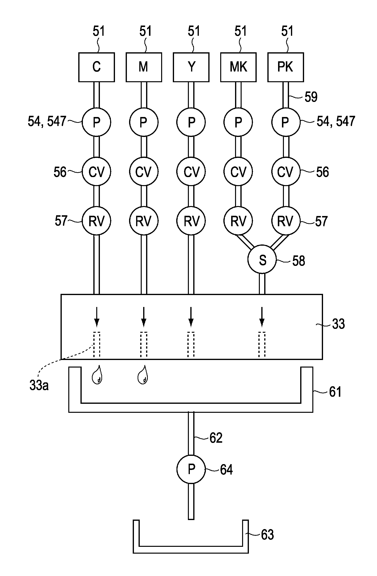
[0107]In the aforementioned embodiments, the ink supply mechanism 50 is a flow-passage pump which may control a discharging ink amount. The ink supply mechanism 50 is a flow-passage pump 54, so-called a diaphragm pump, which is configured to have a diaphragm 542 capable of flexing a pump chamber 544A which suctions the ink at the time of expansion in an internal volume due to an externally applied force and discharges the ink at the time of contraction in the internal volume due to an externally applied force. However, besides the diaphragm pump, any pump which is controlled to suction the ink from the ink cartridge 51 and to discharge a predetermined ink amount may be used as the flow-passage pump 54.

[0108]For example, a reciprocating movement pump such as a piston pump and a plunger pump and a rotary p...


PUM


Abstract

A liquid ejecting apparatus includes a liquid ejecting head with one nozzle group for ejecting one type liquid and another nozzle group for ejecting two types of liquid, thereby ejecting multiple types of liquid from the nozzle groups. A cap forms a sealing space that is suctioned by a suction pump. Flow-passages supply the liquid from a liquid container toward the liquid ejecting head. Flow-passage pumps in the downstream side of the liquid container in the flow-passages suction the liquid from the liquid container and discharge the liquid toward the downstream side. A choke valve has a valve chamber at the downstream side of the flow-passage pump to allow the liquid to flow therein. A flexible member changes a volume of the valve chamber by flexing. A discharge hole in an inner portion of the valve chamber is opened or closed by the flexing of the flexible member.

Description

BACKGROUND[0001]1. Technical Field[0002]The invention relates to a liquid ejecting apparatus and a liquid providing method.[0003]2. Related Art[0004]JP-A-2004-299292 discloses an initial providing manipulation for providing plural types of liquid, which are in a vapor state at the time of staring an initial use of an apparatus, into a plurality of liquid supply passages. A controller disclosed in JP-A-2004-299292 first allows some of a plurality of valve units to be in an opened state and allows all the remaining valve units to be in a closed state. Next, only the liquid supply passages corresponding to the valve units in the opened state are allowed to be precedingly charged. If the preceding charge is completed, the valve units in the opened state is allowed to be closed, and at least a portion of the remaining valve units in the closed state is allowed to be opened to charge the corresponding liquid supply passages.[0005]In addition, JP-A-2008-126408 discloses a configuration whe...

Claims


Application Information

Patent Timeline
Patent Type & Authority Patents(United States)
IPC IPC(8): B41J29/38
CPCB41J2/17596B41J2/16532
Inventor ITO, HIROYUKIKIMURA, HITOTOSHI
Owner SEIKO EPSON CORP
Why Eureka
Try Eureka