Method for transmitting and receiving data in wireless communication system
a wireless communication system and wireless communication technology, applied in the field can solve the problems of waste of radio resources and inability to use resources consecutively, and achieve the effects of reducing overhead, improving efficiency of wireless communication systems, and efficiently utilizing radio resources
- Summary
- Abstract
- Description
- Claims
- Application Information
AI Technical Summary
Benefits of technology
Problems solved by technology
Method used
Image
Examples
first embodiment
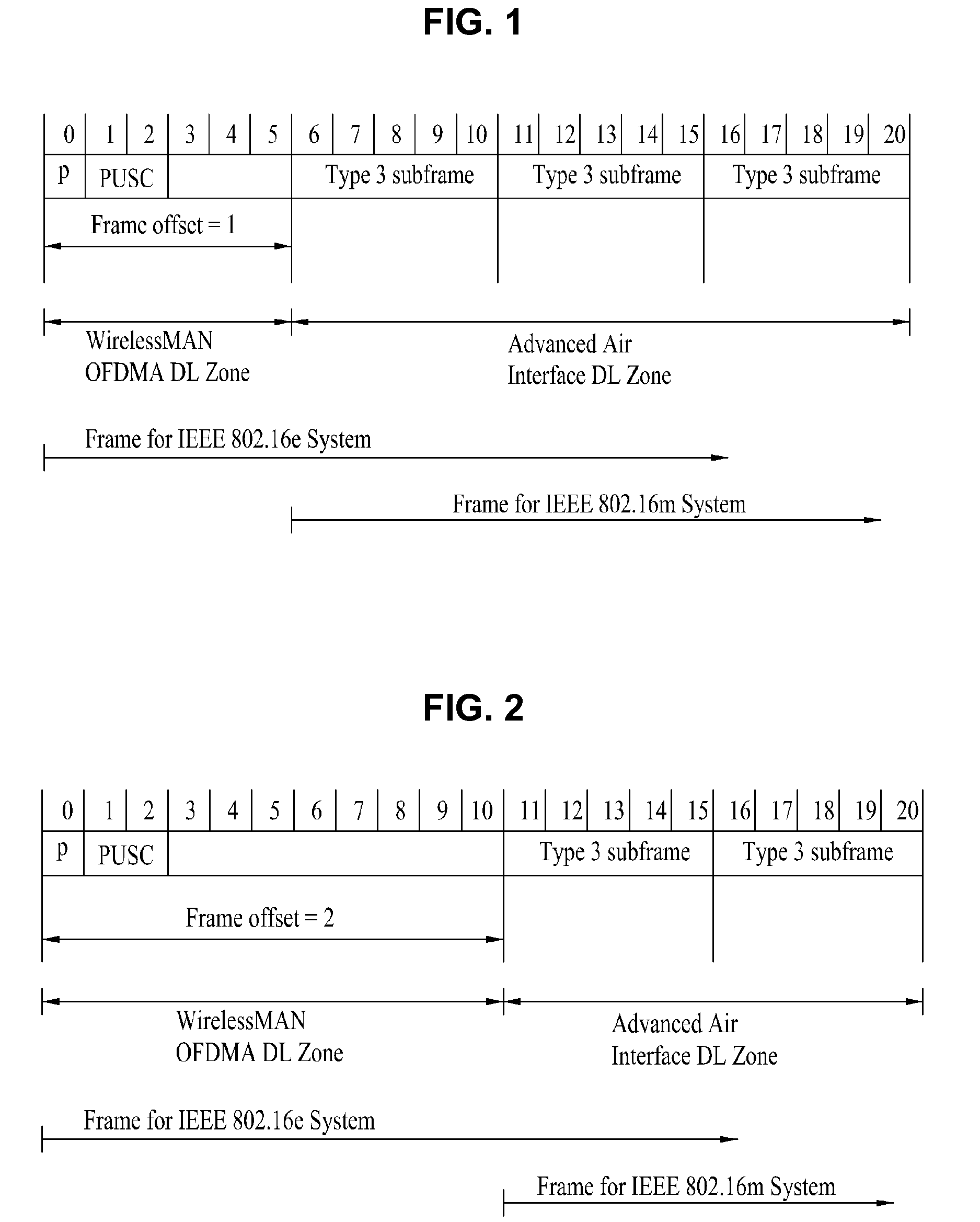
[0050]Next, a method of transmitting data to a terminal supporting a first system and a terminal supporting a second system at a base station of a wireless communication system according to the present invention will be described with reference to FIGS. 4 and 5.
[0051]According to the present embodiment of the present invention, the base station divides a plurality of downlink subframes included in a frame into a first zone and a second zone, transmits a downlink signal to a terminal supporting a first system through the first zone, and transmits a downlink signal to a terminal for a second system through the second zone.
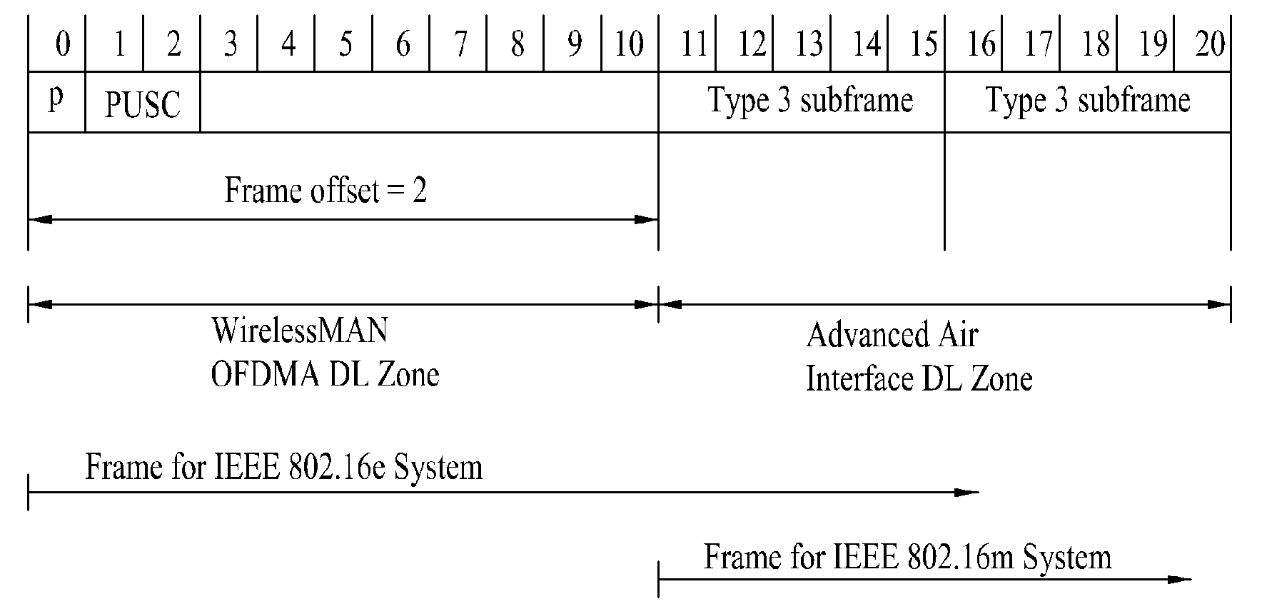
[0052]A downlink frame structure according to the first embodiment of the present invention will be described with reference to FIGS. 4 and 5.
[0053]FIG. 4 is a diagram showing a downlink frame structure according to the first embodiment of the present invention in the case where a frame offset is 1 and FIG. 5 is a diagram showing a downlink frame structure according ...
second embodiment
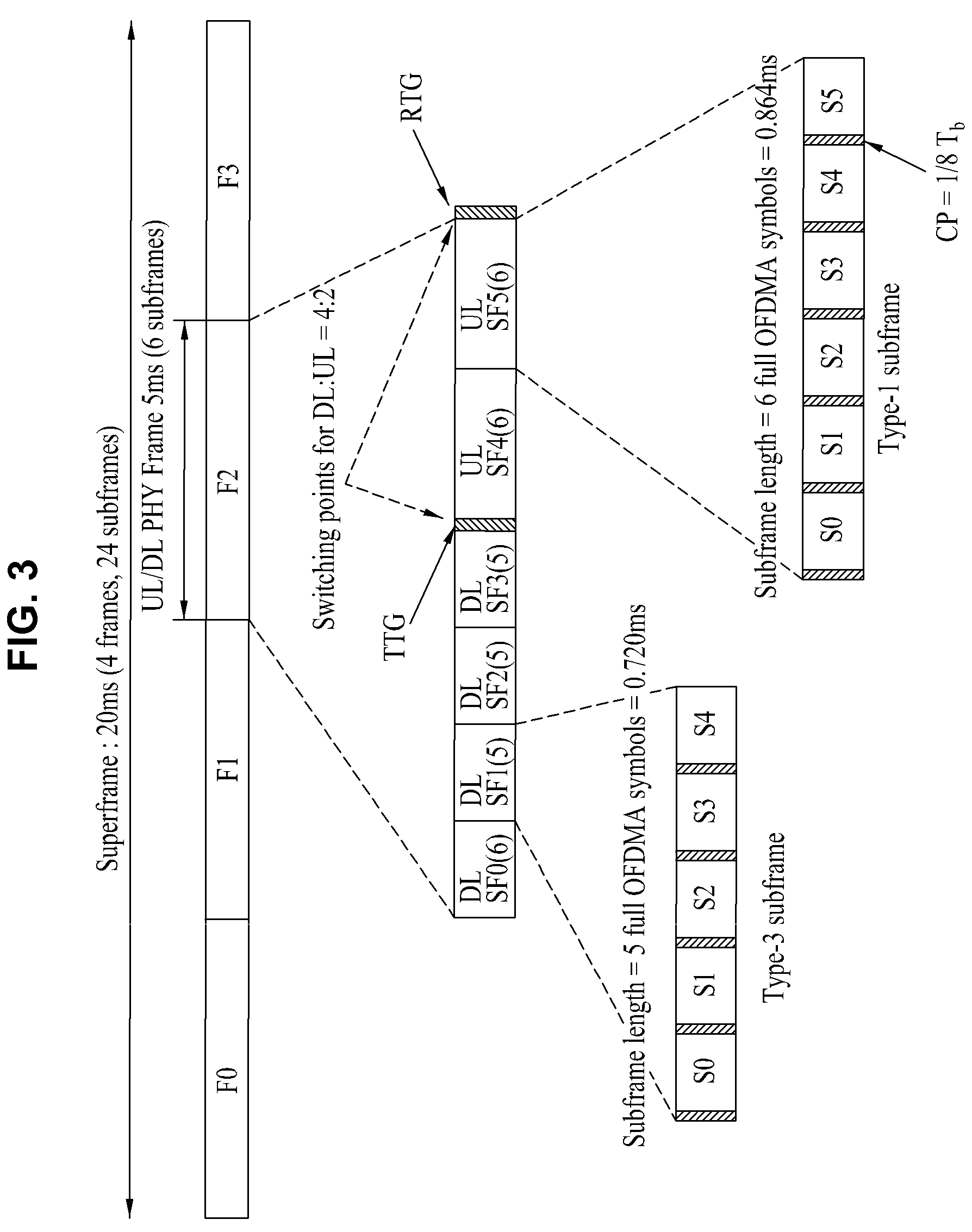
[0062]As shown in FIG. 6, a downlink subframe includes 21 OFDM symbols if the ratio of downlink to uplink subframes is 4:2. The downlink frame according to the present invention includes three type 3 subframes and one type 1 subframe.
[0063]A first subframe of a second zone is a type 1 subframe and the other subframes thereof are type 3 subframes. The first zone include 5*(frame offset) OFDM symbols.
[0064]Next, a method of transmitting data to a terminal supporting a first system and a terminal supporting a second system at a base station of a wireless communication system according to a third embodiment of the present invention will be described with reference to FIG. 7. FIG. 7 is a diagram showing a downlink frame structure according to the third embodiment of the present invention in the case where a frame offset is 1.
[0065]Although FIG. 7 shows the downlink frame in the case where a ratio of downlink to uplink subframes is 4:2, the present invention is not limited thereto.
[0066]A...
fourth embodiment
[0070]As shown in FIG. 8, the downlink subframe includes 21 OFDM symbols if the ratio of downlink to uplink subframes is 4:2. The downlink frame according to the present invention includes one type 4 subframe and two type 1 subframes.
[0071]All subframes included in the second zone are type 1 subframes. The first zone includes 9+6*(frame offset-1) OFDM symbols.
[0072]The embodiments of the present invention can be implemented by a variety of means, for example, hardware, firmware, software, or a combination thereof. In the case of implementing the present invention by hardware, the method of transmitting and receiving the data according to the embodiment of the present invention can be implemented with application specific integrated circuits (ASICs), Digital signal processors (DSPs), digital signal processing devices (DSPDs), programmable logic devices (PLDs), field programmable gate arrays (FPGAs), a processor, a controller, a microcontroller, a microprocessor, etc.
[0073]If operatio...
PUM
 Abstract
Description
Claims
Application Information
 - R&D
- Intellectual Property
- Life Sciences
- Materials
- Tech Scout
- Unparalleled Data Quality
- Higher Quality Content
- 60% Fewer Hallucinations
Browse by: Latest US Patents, China's latest patents, Technical Efficacy Thesaurus, Application Domain, Technology Topic, Popular Technical Reports.
© 2025 PatSnap. All rights reserved.Legal|Privacy policy|Modern Slavery Act Transparency Statement|Sitemap|About US| Contact US: help@patsnap.com


