
Twinaxial linear induction antenna array for increased heavy oil recovery

a technology of heavy oil recovery and induction antenna array, which is applied in the direction of insulation, immersion heating arrangement, and wellbore/well accessories, etc., can solve the problems of slow and unreliable steam enhanced oil recovery, inability to extract standard crude oil, and inability to drill and refine the method used in extracting standard crude oil

Active Publication Date: 2013-05-21
HARRIS CORP
View PDF149 Cites 14 Cited by
  • Summary
  • Abstract
  • Description
  • Claims
  • Application Information

AI Technical Summary

Problems solved by technology

Because of the extremely high viscosity of bituminous ore, oil sands, oil shale, tar sands, and heavy oil, the drilling and refinement methods used in extracting standard crude oil are typically not available.
Steam enhanced oil recovery may not be suitable for permafrost regions due to surface melting, in stratified and thin pay reservoirs with rock layers, and where there is insufficient caprock.
Well start up, for example, the initiation of the steam convection, may be slow and unreliable as conducted heating in hydrocarbon ores is slow.

Method used


Image

  • Twinaxial linear induction antenna array for increased heavy oil recovery
  • Twinaxial linear induction antenna array for increased heavy oil recovery
  • Twinaxial linear induction antenna array for increased heavy oil recovery

Examples


Embodiment Construction

[0023]The subject matter of this disclosure will now be described more fully, and one or more embodiments of the invention are shown. This invention may, however, be embodied in many different forms and should not be construed as limited to the embodiments set forth herein. Rather, these embodiments are examples of the invention, which has the full scope indicated by the language of the claims.

[0024]Radio frequency (RF) heating is heating using one or more of three energy forms: electric currents, electric fields, and magnetic fields at radio frequencies. Depending on operating parameters, the heating mechanism may be resistive by joule effect or dielectric by molecular moment. Resistive heating by joule effect is often described as electric heating, where electric current flows through a resistive material. Dielectric heating occurs where polar molecules, such as water, change orientation when immersed in an electric field. Magnetic fields also heat electrically conductive material...


PUM


Abstract

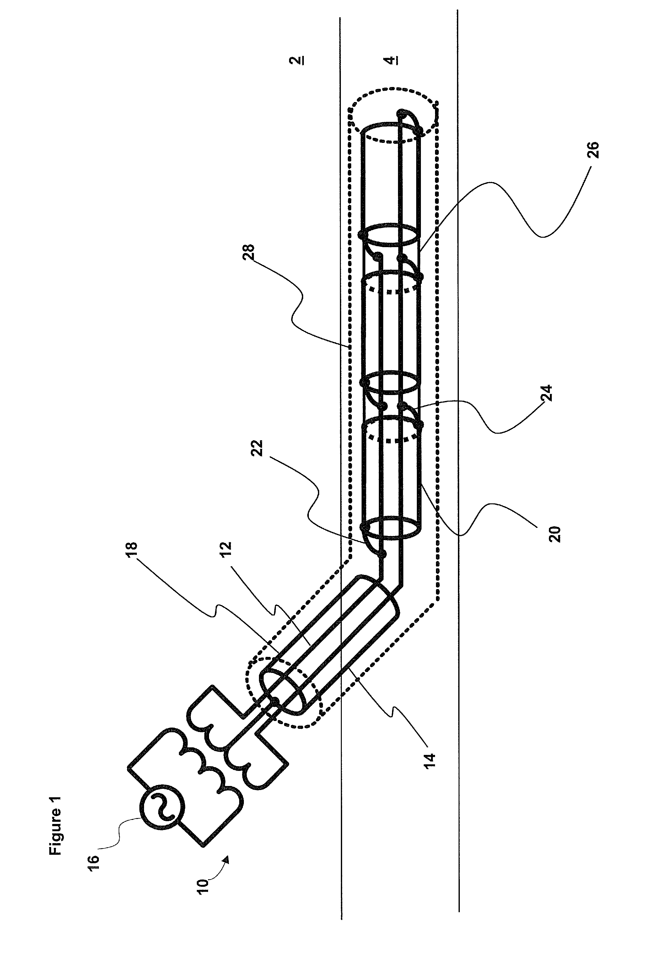
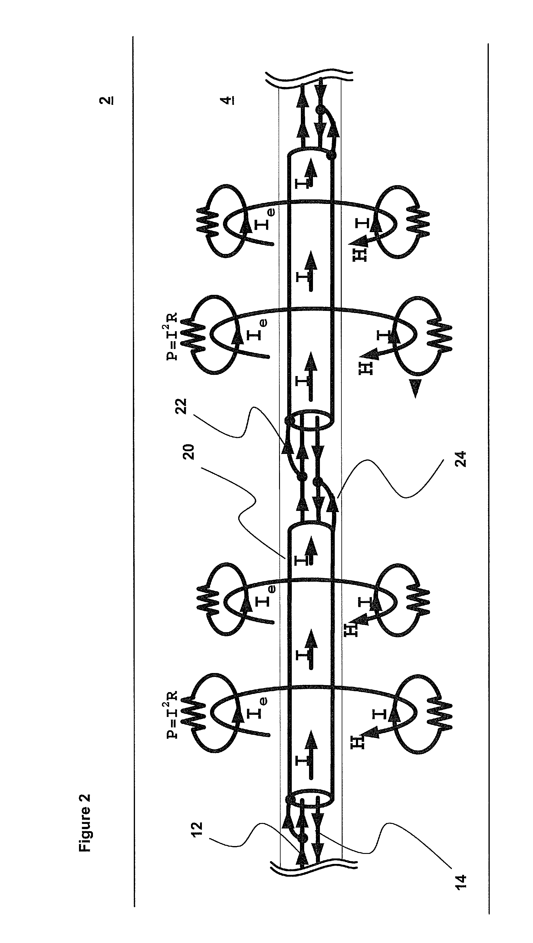
A radio frequency applicator and method for heating a hydrocarbon formation is disclosed. An aspect of at least one embodiment disclosed is a linear radio frequency applicator. It includes a transmission line and a current return path that is insulated from the transmission line. At least one conductive sleeve is positioned around the transmission line and the current return path. The transmission line and the current return path are electrically connected to the conductive sleeve. A radio frequency source is configured to apply a signal to the transmission line. When the linear applicator is operated, a circular magnetic field forms, which creates eddy current in the formation causing heavy hydrocarbons to flow. The heat is reliable as liquid water contact is not required. The applicator may operate in permafrost regions and without caprock.

Description

CROSS REFERENCE TO RELATED APPLICATIONS[0001]This specification is related to the patent application identified by Harris Corporation Ser. No. 12 / 950,405, which is incorporated by reference here.BACKGROUND OF THE INVENTION[0002]The present invention relates to heating a geological formation for the extraction of hydrocarbons, which is a method of well stimulation. In particular, the present invention relates to an advantageous radio frequency (RF) applicator and method that can be used to heat a geological formation to extract heavy hydrocarbons.[0003]As the world's standard crude oil reserves are depleted, and the continued demand for oil causes oil prices to rise, oil producers are attempting to process hydrocarbons from bituminous ore, oil sands, tar sands, oil shale, and heavy oil deposits. These materials are often found in naturally occurring mixtures of sand or clay. Because of the extremely high viscosity of bituminous ore, oil sands, oil shale, tar sands, and heavy oil, the...

Claims


Application Information

Patent Timeline
Patent Type & Authority Patents(United States)
IPC IPC(8): E21B36/04E21B43/24
CPCE21B43/2401H01Q1/04H05B2214/03
Inventor PARSCHE, FRANCIS EUGENE
Owner HARRIS CORP
Learn More