Eureka AIR delivers breakthrough ideas for toughest innovation challenges, trusted by R&D personnel around the world.

Mobile lighting apparatus

Active Publication Date: 2013-05-14
STRAY LIGHT OPTICAL TECH
View PDF54 Cites 29 Cited by
  • Summary
  • Abstract
  • Description
  • Claims
  • Application Information

AI Technical Summary

Benefits of technology

[0003]The present disclosure relates to a mobile lighting apparatus which is easily positionable to illuminate indoor or outdoor locations. More particularly, t

Problems solved by technology

Reduction of carbon dioxide and particulate matter emission

Method used


Image

  • Mobile lighting apparatus
  • Mobile lighting apparatus
  • Mobile lighting apparatus

Examples


Example

DETAILED DESCRIPTION OF THE DRAWINGS

[0037]For the purposes of promoting an understanding of the principles of the present disclosure, reference will now be made to the embodiments illustrated in the drawings, which are described below. The embodiments disclosed below are not intended to be exhaustive or limit the present system to the precise form disclosed in the following detailed description. Rather, the embodiments are chosen and described so that others skilled in the art may utilize their teachings. Therefore, no limitation of the scope of the claimed present system is thereby intended. The present system includes any alterations and further modifications of the illustrated devices, systems and described methods and further applications of the principles of the present disclosure which would normally occur to one skilled in the art. Corresponding reference characters indicate corresponding parts throughout the several views.

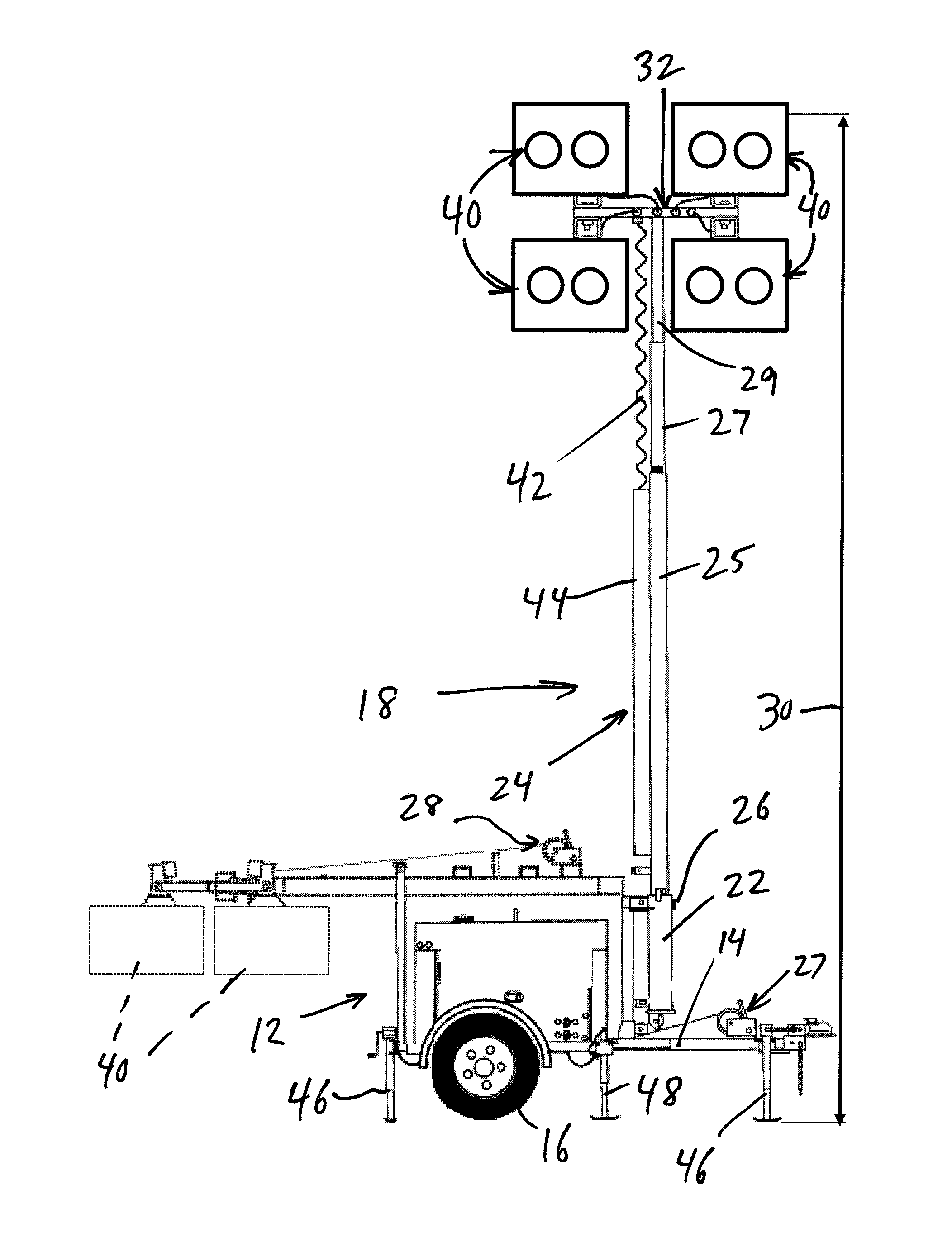
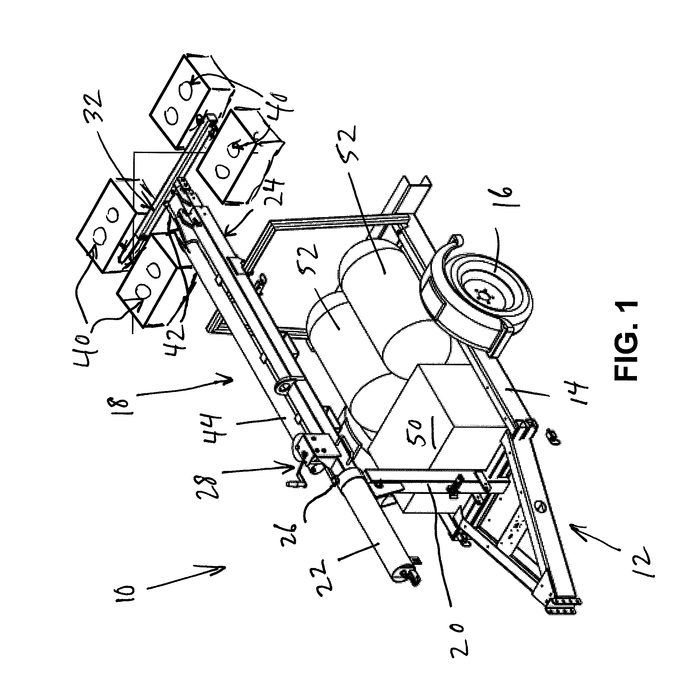
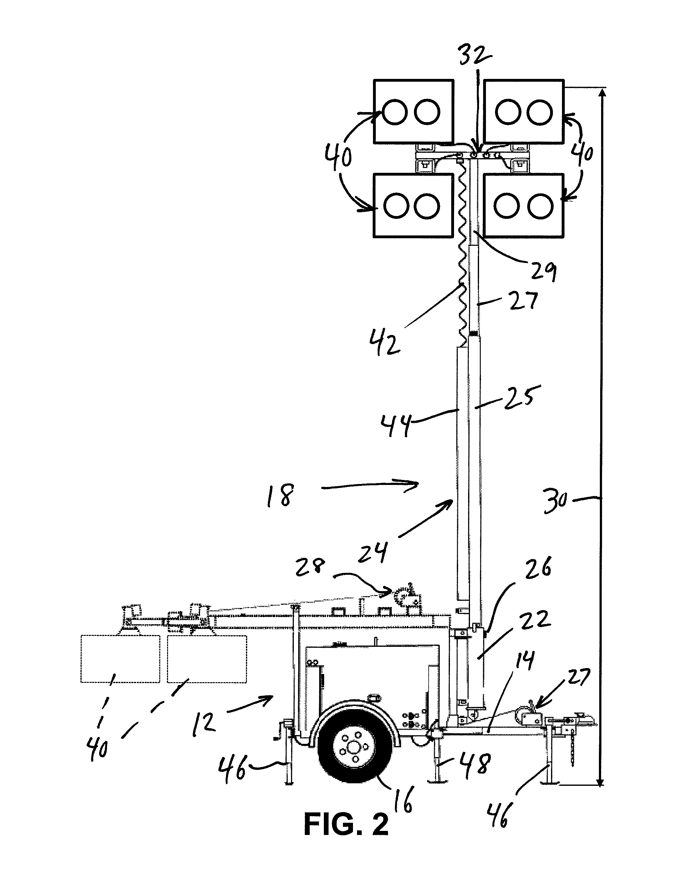
[0038]Referring now to the drawings, FIGS. 1 and 2 il...


PUM


Abstract

A mobile lighting apparatus includes a portable frame such as a moveable trailer or skid having a light tower thereon. The light tower is moveable from a stowed position to a deployed position. A hydrogen-powered fuel cell is located on the portable frame to provide electrical power to an array of the energy efficient lights located on the light tower.

Description

CROSS REFERENCE TO RELATED APPLICATION[0001]This application claims the benefit of U.S. Provisional Application Ser. No. 61 / 176,103, filed on May 6, 2009, which is expressly incorporated by reference.NOTICE[0002]This invention was made in part with government support under Contract No. DE-AC04-94AL85000 awarded by the U.S. Department of Energy to Sandia Corporation. The government has certain rights in the invention.BACKGROUND AND SUMMARY[0003]The present disclosure relates to a mobile lighting apparatus which is easily positionable to illuminate indoor or outdoor locations. More particularly, the present disclosure relates to a mobile lighting apparatus which greatly reduces noise and harmful emissions compared to conventional mobile lighting systems.[0004]The mobile lighting apparatus of the present disclosure includes a portable frame such as a moveable trailer or skid having a light tower thereon. The light tower is moveable from a stowed position to a deployed position. A hydro...

Claims


Application Information

Patent Timeline
IPC IPC(8): B60Q1/00B60Q3/00
CPCF21V11/183F21V29/773F21S2/005F21V7/041F21V21/30F21V23/008F21V23/026F21V7/00H01J61/523H01J65/042F21V23/007H01J61/025F21V29/15F21V29/507F21V29/763F21V29/004F21S2/00F21V21/06F21W2131/1005F21W2131/105F21Y2101/02F21V29/74F21Y2101/00F21Y2115/10
Inventor ROE, GEORGE MICHAELKLEBANOFF, LEONARD ELLIOTTREA, GERALD W.DRAKE, ROBERT A.JOHNSON, TERRY A.WINGERT, STEVEN JOHNDAMBERGER, THOMAS A.SKRADSKI, THOMAS J.RADLEY, CHRISTOPHER JAMESOROS, JAMES M.SCHUTTINGER, PAUL G.GRUPP, DAVID J.PREY, STEPHEN CARL
Owner STRAY LIGHT OPTICAL TECH
Why Eureka
Eureka Blog
Learn More