
Electromagnetic actuator and valve

a technology of electromagnets and actuators, applied in the direction of electromagnets, cores/yokes, pipe elements, etc., can solve the problem of relatively high manufacturing effor

Inactive Publication Date: 2013-05-07
DANFOSS AS
View PDF33 Cites 8 Cited by
  • Summary
  • Abstract
  • Description
  • Claims
  • Application Information

AI Technical Summary

Benefits of technology

This design allows for extensive control opportunities with reduced manufacturing complexity, enabling a multi-stage drive mechanism for valve operation using different current intensities, with one armature acting as an on / off controller and the other as a proportional controller, effectively managing valve opening and flow.

Problems solved by technology

However, the effort to be invested in the manufacturing is relatively high.

Method used


Image

  • Electromagnetic actuator and valve
  • Electromagnetic actuator and valve
  • Electromagnetic actuator and valve

Examples


Embodiment Construction

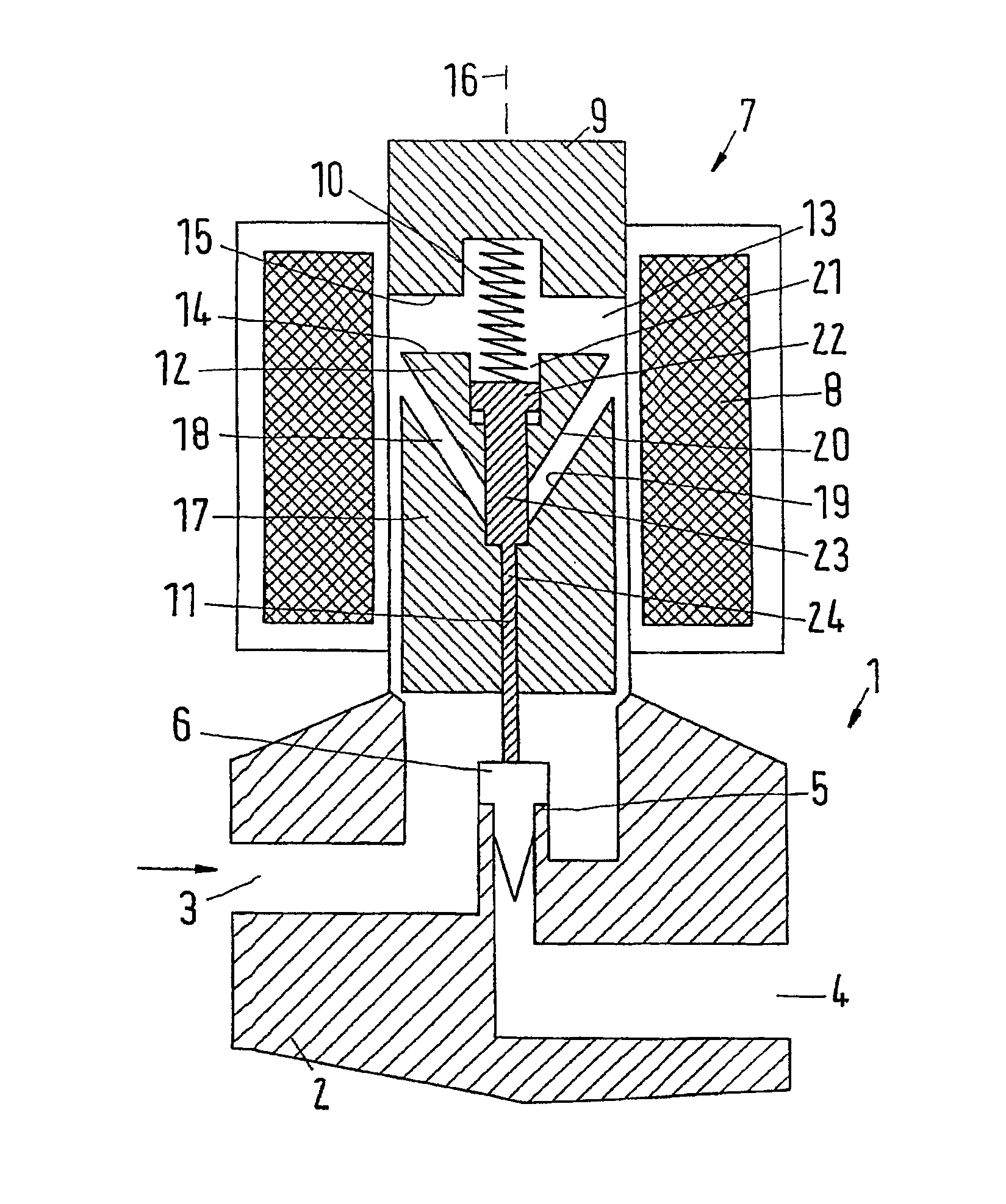
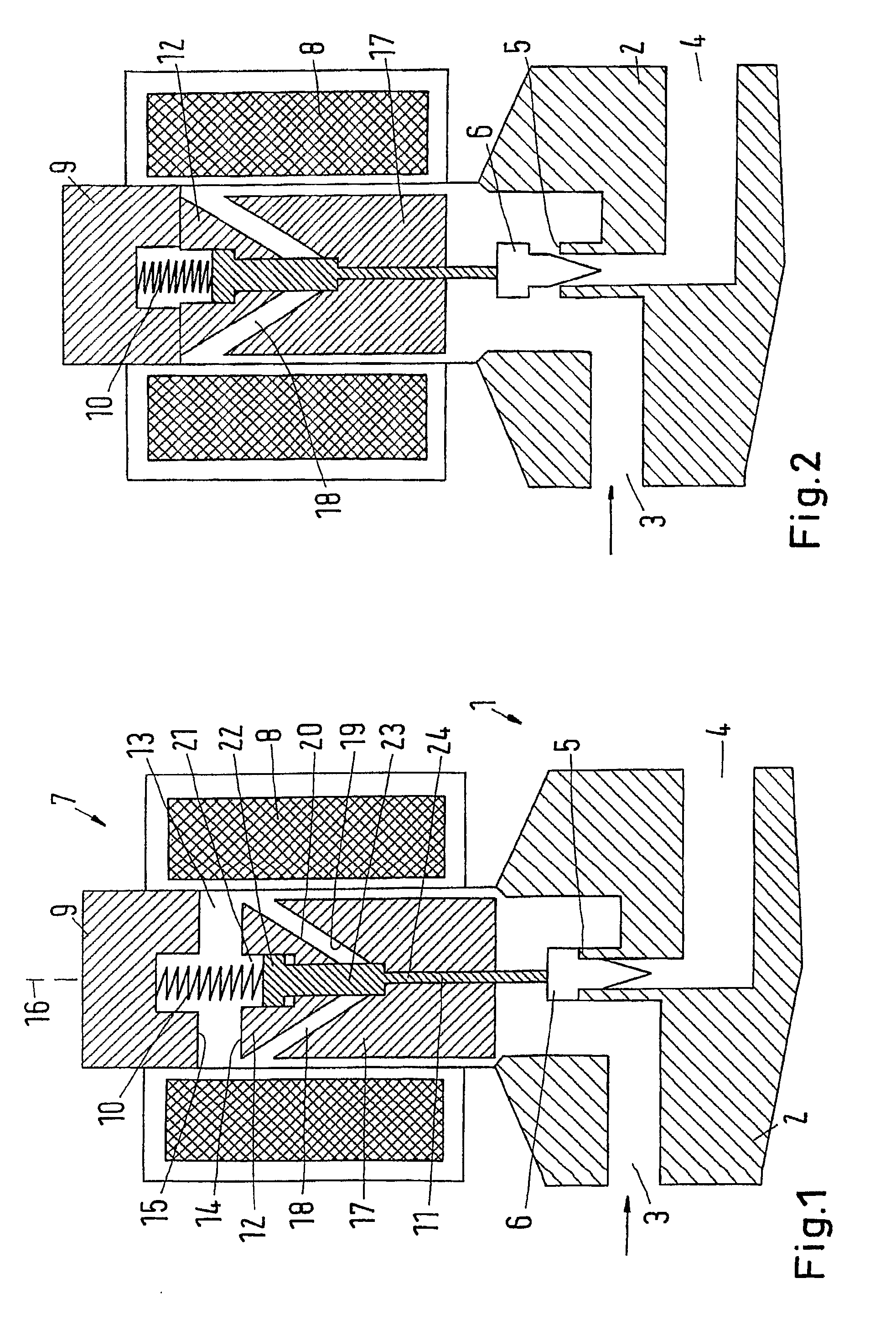
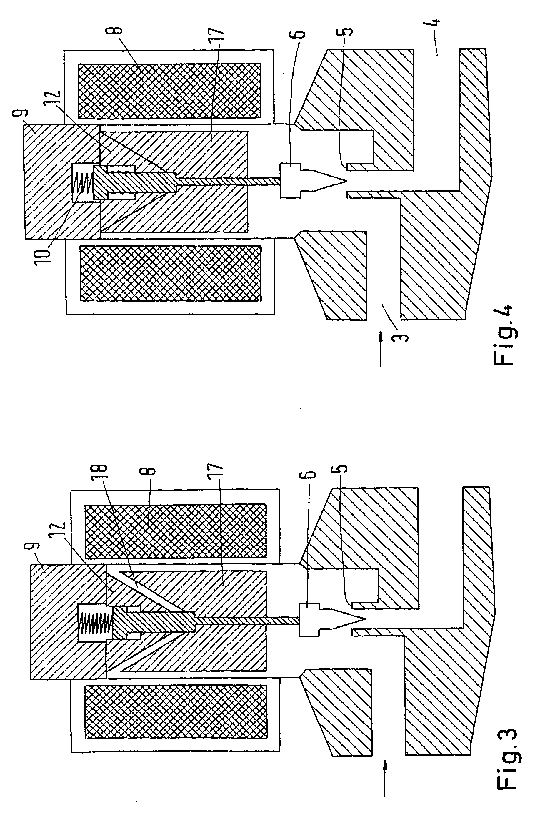
[0034]FIG. 1 is a schematic view of a valve 1 with a valve housing comprising an inlet 3, an outlet 4 and a valve seat 5 there between. When the valve 1 is closed, a valve element 6 rests on the valve seat 5. When the valve is open, the valve element 6 is lifted more or less off from the valve seat 5 (FIGS. 2 to 4).

[0035]For the actuation of the valve element 6, an electromagnetic actuator 7 is provided, which is connected to the valve housing 2.

[0036]The actuator 7 comprises one single coil 8 that can be supplied with current in a manner not shown in detail, the intensity of this current being adjustable. By means of the intensity of the current, also the intensity of a magnetic field and thus the intensity of the magnetic flux generated by the coil 8 can be adjusted.

[0037]On a front end of the coil 8 an stationary armature 9 that can also be called a “yoke” is arranged. The armature 9 serves as counter flange for a closing spring 10 that acts upon a transmission element 11 that is...


PUM


Abstract

The invention concerns an electromagnetic actuator (7) with a coil (8) and at least two armatures (12, 17) being movable along an axis (16) and being acted upon by a magnetic field generated by the coil (8). It is endeavoured to achieve large control opportunities by simple means. For this purpose, it is provided that one armature (12) is acted upon by a larger drive force from the magnetic field than another armature (17).

Description

CROSS REFERENCE TO RELATED APPLICATIONS[0001]This application is entitled to the benefit of and incorporates by reference essential subject matter disclosed in International Patent Application No. PCT / DK2009 / 000053 filed on Feb. 26, 2009 and German Patent Application No. DE 10 2008 011 573.8 filed Feb. 28, 2008.FIELD OF THE INVENTION[0002]The invention concerns an electromagnetic actuator with a coil and at least two armatures being movable along an axis and being acted upon by a magnetic field generated by the coil.[0003]Further, the invention concerns a valve with an inlet, an outlet and, between them, a valve seat that interacts with a valve element.BACKGROUND OF THE INVENTION[0004]Such an electromagnetic actuator and a valve are, for example, known from EP 0 763 683 A1. Inside the coil are arranged two armatures, which can move along the central axis of the coil, when the coil is acted upon by a current and accordingly generates a magnetic field. The magnetic field causes that t...

Claims


Application Information

Patent Timeline
Patent Type & Authority Patents(United States)
IPC IPC(8): F16K31/10
CPCF16K31/06F16K31/0655H01F7/081H01F7/13F16K31/0675H01F2007/086
Inventor BIRKELUND, MICHAEL
Owner DANFOSS AS
Learn More