
Pressurised aircraft door equipped with a vent flap

a technology of aircraft doors and vents, applied in the field of doors, can solve the problems of introducing a particularly severe safety risk to the blocking device, the risk of the locking device being frozen, and the operation of this type of device is relatively complex

Inactive Publication Date: 2013-05-07
AIRBUS OPERATIONS INC AS A
View PDF13 Cites 9 Cited by
  • Summary
  • Abstract
  • Description
  • Claims
  • Application Information

AI Technical Summary

Benefits of technology

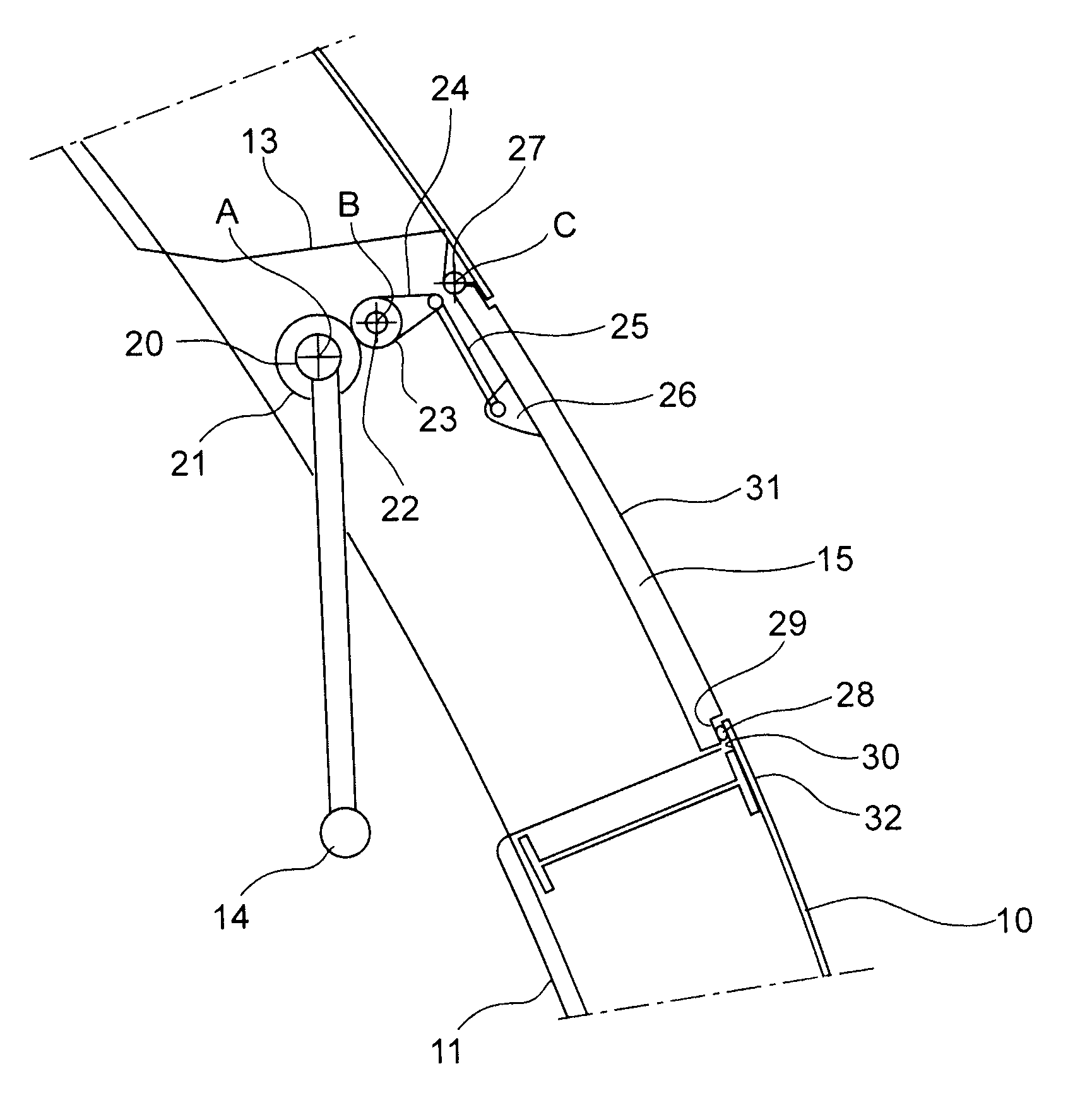
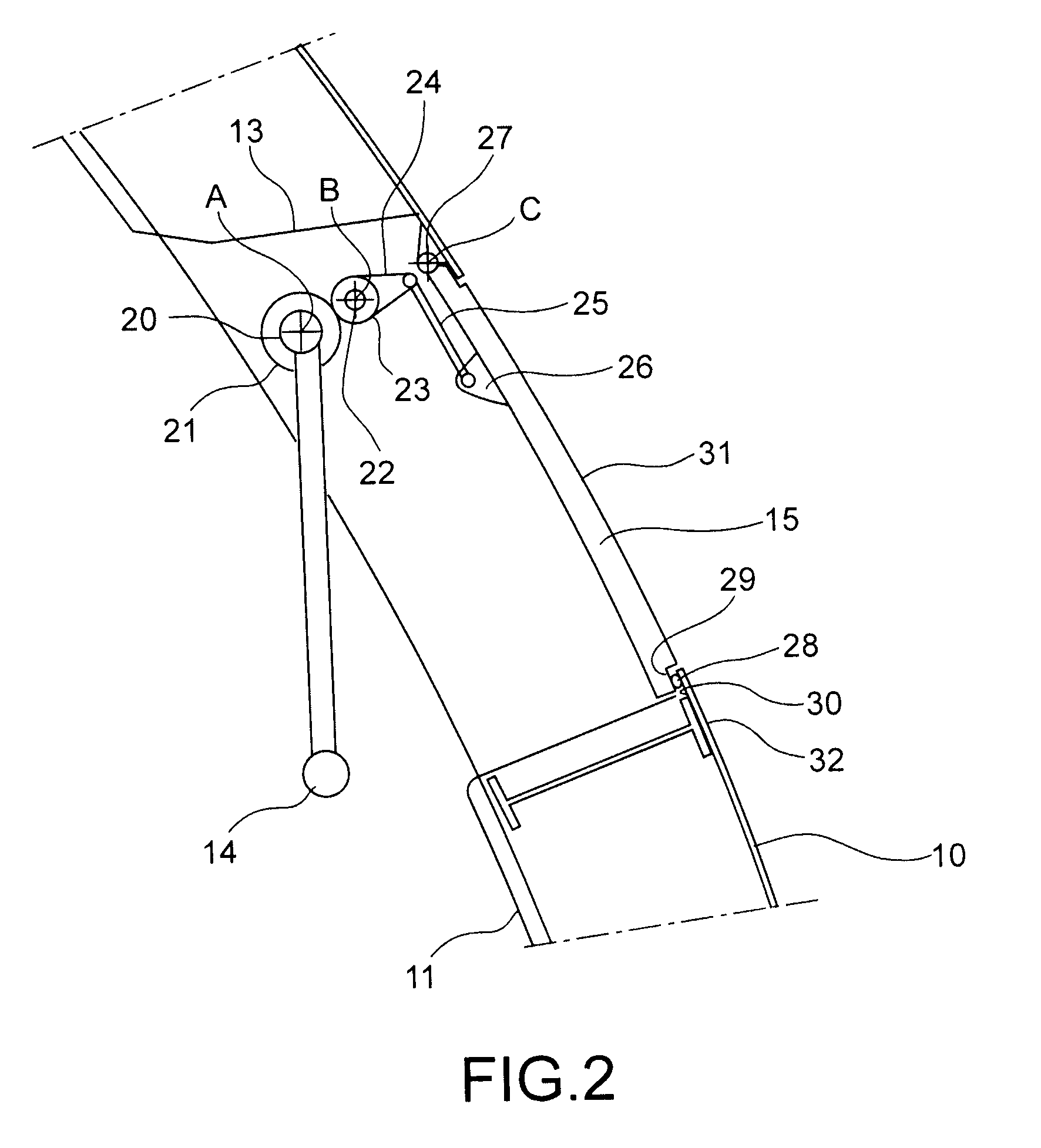
[0017]Thus, the invention effectively minimises the risks of the ingress of precipitation inside the aircraft, while venting the aircraft before the door is unlocked. When the door is in its open position, the flap is in a closing position of said opening window so as to prevent the ingress of any precipitation inside the aircraft. Furthermore, when the door is opened and before the unlocking step, the flap is in an open position in which the aircraft is vented. Any risk of sudden opening of the door under the effect of residual pressure is thus avoided.
[0021]Advantageously, the flap occupies its closing position of said opening window before the control member moves into its second end position putting the door in its open position. Thus, when positioning the control member in its second end position, a closing force is applied to the flap that tends to close the flap even more which improves the closing seal of the opening window by the flap.
[0023]Thus, when the aircraft is pressurised and the pressure inside the aircraft is greater than the external pressure, particularly in flight and particularly at high altitude, the pressure difference generates a large force on the flap that is transmitted directly to the control member so as to hold it in its first end position. Thus, the differential pressure prevents any movement of the control member and holds the door in its closed / locked position. This prevents any deliberate or accidental opening of the aircraft door during these flight conditions.
[0024]The invention also has another advantage that avoids firstly the use of locking means dedicated to locking the door in flight, and secondly to eliminate the need to use a specifically designed handle to operate the flap. This satisfies the requirement to save mass, which is essential for aircraft performances.
[0026]It is advantageous if the control member includes a gear in order to amplify the pressure force applied to the control member flap.
[0028]It is also advantageous if the door comprises a plurality of normally closed opening windows each closed by a vent flap. Thus, the area through which the aircraft is vented is increased. This reduces the time necessary to equalise internal and external pressures, thus optimising the minimum door opening time.

Problems solved by technology

However, there is a serious risk of these locking devices becoming frozen during prolonged cruising flight.
It is easy to understand that operation of this type of device is relatively complex, and that blocking of the device introduces a particularly severe safety risk.
Furthermore, this device is dedicated solely to locking the door, which creates an additional mass that penalises aircraft performances.
Other problems are related to pressurisation of the aircraft or an aircraft compartment.
One of these problems is related to the residual pressure that may remain within the aircraft before the door is opened.
This residual pressure may cause a sudden outwards movement of the door when it is opened, which can cause an accident to persons, particularly if the door is opened from outside the aircraft.
Furthermore, the internal pressure in the aircraft must normally be limited to a safe value, as long as the door is not completely closed and locked.
Secondly, it is only possible to close the flap after the door has been closed and locked.
However, some problems remain unsolved by this technical solution proposed up to now.
One of these problems relates to opening the vent flap.
The risk of ingress of precipitation (rain, snow) inside the aircraft, in other words the entry of precipitation through the opening window that is then not closed by the flap, is high.
Precipitation can then freeze in or on the door opening and closing devices and consequently block the aircraft door.
It is then no longer guaranteed that the door can be subsequently opened, possibly during an emergency.

Method used


Image

  • Pressurised aircraft door equipped with a vent flap
  • Pressurised aircraft door equipped with a vent flap
  • Pressurised aircraft door equipped with a vent flap

Examples


Embodiment Construction

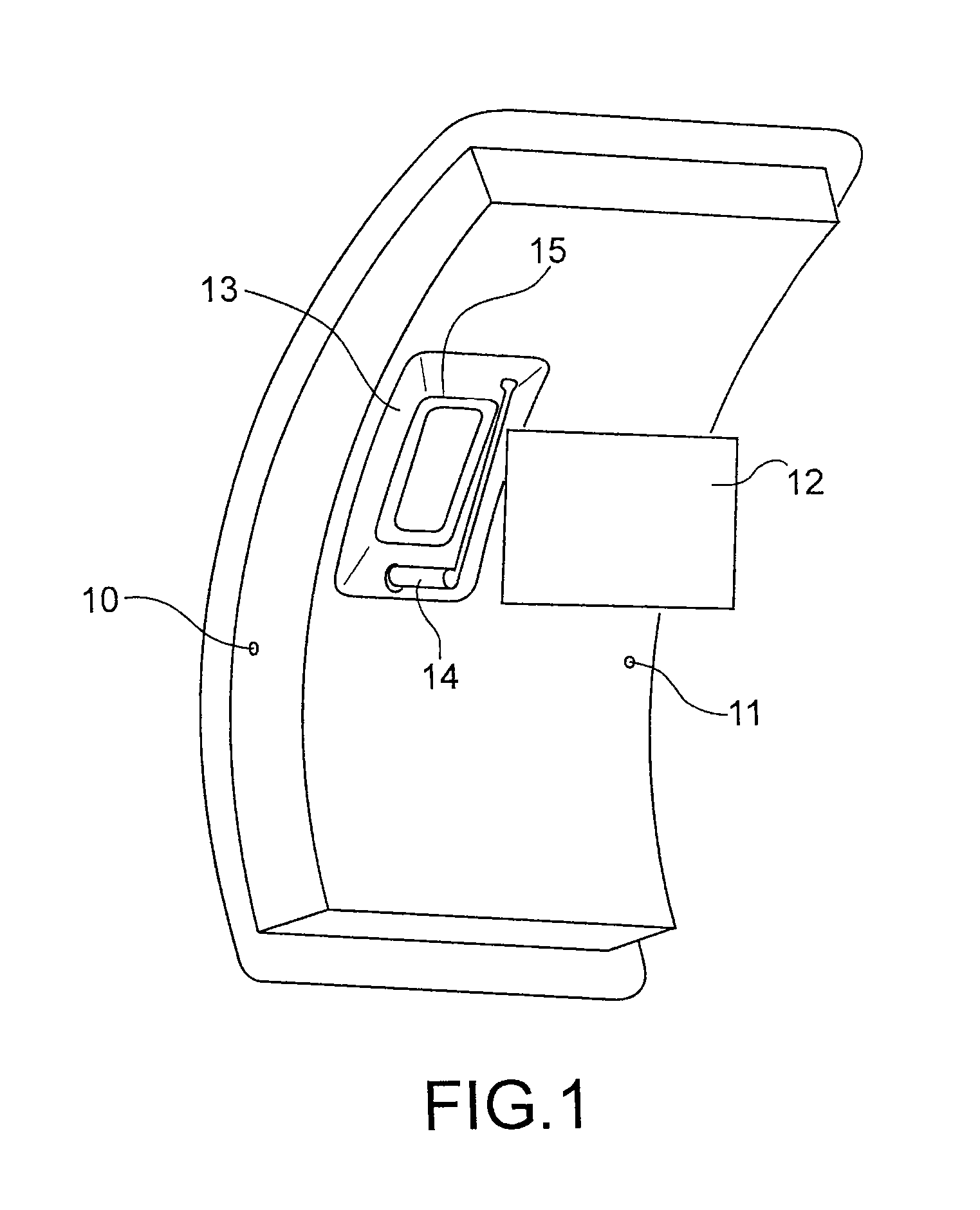
[0034]FIG. 1 diagrammatically shows an aircraft door more specifically intended for use by passengers to enter a pressurised aircraft. However, this type of door is only an example because as already mentioned, the invention is indifferently applicable to all types of aircraft entry or exit doors, regardless of whether these doors are intended for use by passengers, service personnel, baggage, etc.

[0035]The door shown in FIG. 1 comprises a single piece door structure denoted as reference 10, and a frame structure (not shown). An inside cladding 11 is provided that covers the door structure 10.

[0036]The door structure 10 comprises stops (not shown) on its lateral part that bear on facing stops connected to the frame structure, when the door is in its closed and locked position. This characteristic transfers pressure loads from the door structure 10 to the frame structure, and then to the aircraft fuselage. In other words, the stops formed on the lateral part of the door structure 10 ...


PUM


Abstract

The invention relates to a pressurized aircraft door that minimizes risk of ingress of precipitation inside the aircraft, while maintaining venting of the aircraft before unlocking the door. The purpose of the invention is achieved using a vent flap controlled by a door control member and designed such that the flap successively occupies the following positions during the opening movement of the control member: a closed position when the control member occupies a first end position putting the door in a closed / locked position; at least one partially open position before the door is in a closed / unlocked position; then once again in the closed position when the control member occupies a second end position putting the door in an open position.

Description

TECHNICAL FIELD[0001]The invention relates to a door designed to be fitted on a pressurised aircraft.[0002]The aircraft door according to the invention may be used in particular to equip all aircraft exits designed for entry and exit of passengers, and also for service, passage of goods, etc.STATE OF PRIOR ART[0003]Aircraft doors need to satisfy many requirements particularly related to their mechanical strength, leak tightness and safety. Some of these requirements are also fixed by the international regulations in force.[0004]For example, it is essential to prevent accidental opening of an aircraft door when the aircraft is in flight, particularly as a result of deliberate action by a passenger. The conventional way of achieving this is to use automatic locking devices electrically controlled from a plurality of signals indicating that the aircraft is in flight. For example, these signals may correspond to the “retracted” position of landing gears, the value of the internal pressu...

Claims


Application Information

Patent Timeline
Patent Type & Authority Patents(United States)
IPC IPC(8): B64C1/14
CPCB64C1/1407
Inventor DEPEIGE, ALAN
Owner AIRBUS OPERATIONS INC AS A
Learn More