Computer system and method of booting the same
a computer system and computer system technology, applied in the field of computer system and a method of booting a computer system, can solve the problems of inability to efficiently reduce the os boot time, the os data cannot be read in time, and the os is not possible to store the os on the ram that does not utilize a backup battery, so as to achieve efficient reduction of the system boot time
- Summary
- Abstract
- Description
- Claims
- Application Information
AI Technical Summary
Benefits of technology
Problems solved by technology
Method used
Image
Examples
first embodiment
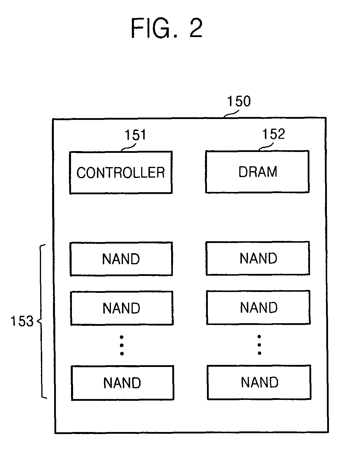
[0037]FIG. 2 illustrates a block diagram of the SSD 150 of FIG. 1 according to a Referring to FIG. 2, the SSD 150 may include a controller 151, a memory 152, and a non-volatile memory block 153.
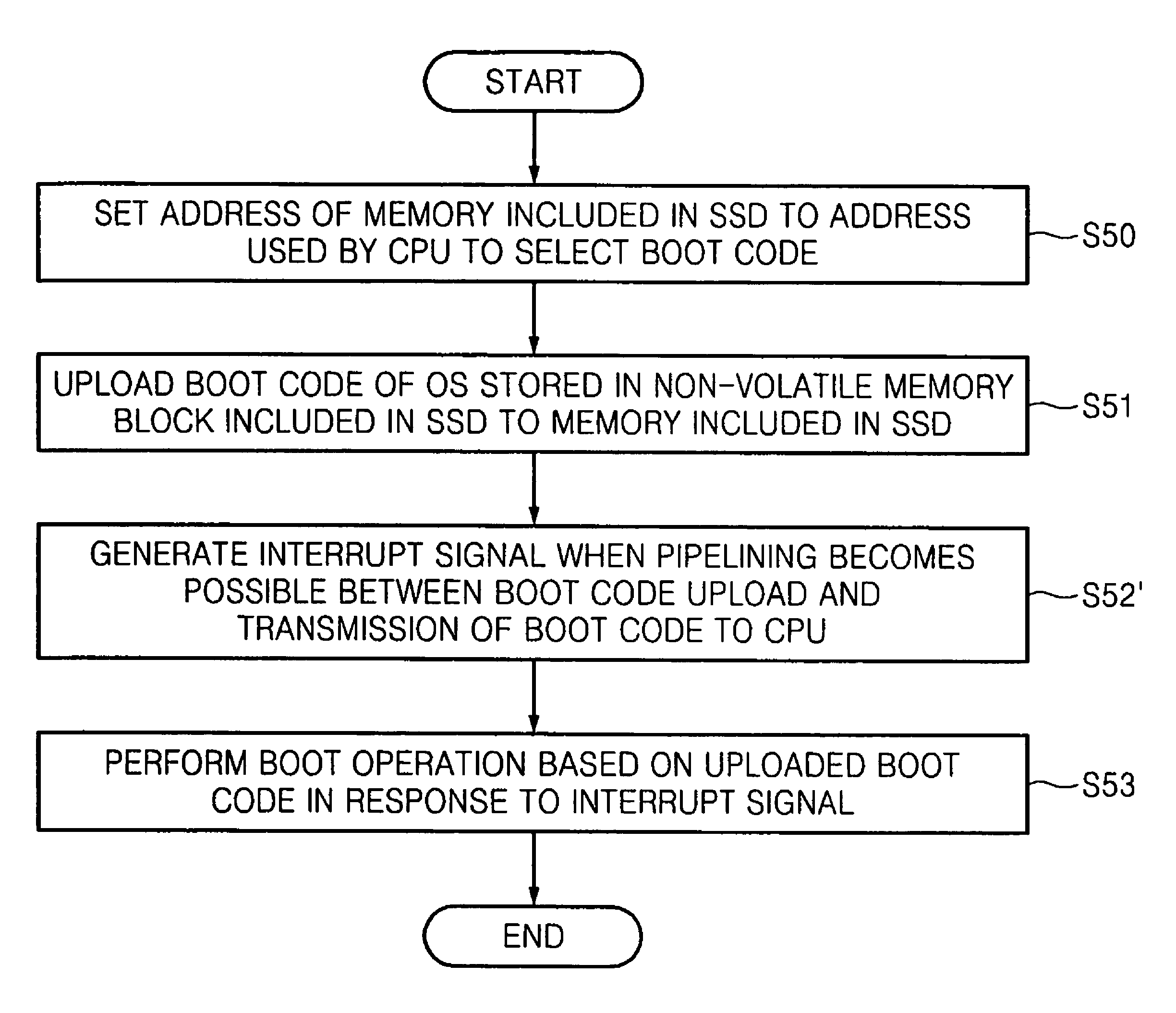
[0038]The controller 151 controls the operation of the SSD 150. The non-volatile memory block 153 stores an operating system (OS), a variety of programs, and a variety of data. When the computer system 100 is powered on, the OS stored in the non-volatile memory block 153 is uploaded to the memory 152 and then the computer system 100 performs the boot operation based on the OS uploaded to the memory 152. The memory 152 and the non-volatile memory block 153 may be implemented by dynamic random access memory (DRAM), which is volatile, and a NAND flash memory block, respectively. The present inventive concept is not restricted to the current embodiment.
[0039]In particular, the controller 151 may upload the OS stored in the non-volatile memory block 153 to the memory 152 when the computer system ...
second embodiment
[0047]FIG. 3 illustrates a block diagram of the SSD 150′ illustrated in FIG. 1 according to a Referring to FIG. 3, an SSD 150′ may include the controller 151, a memory 152′ and the non-volatile memory block 153. The elements referred to by like numbers in FIGS. 2 and 3 have the same structure and function. Thus, detailed description thereof will be omitted and only differences between the SSD 150 illustrated in FIG. 2 and the SSD 150′ illustrated in FIG. 3 will be described.
[0048]Unlike the memory 152 illustrated in FIG. 2, the memory 152′ illustrated in FIG. 3 is implemented by volatile memory including a plurality of channels. For instance, the memory 152′ may be implemented by volatile memory with at least two channels, e.g., OneDRAM which is a fusion memory chip manufactured by Samsung. In this case, the boot code may be uploaded from the non-volatile memory block 153 to the memory 152′ through a first channel and, simultaneously, the boot code uploaded to the memory 152′ may b...
third embodiment
[0049]FIG. 4 illustrates a block diagram of the SSD 150″ illustrated in FIG. 1 according to a Referring to FIG. 4, an SSD 150″ may include the controller 151, a memory 152″, and the non-volatile memory block 153. The elements referred to by like numbers in FIGS. 2 and 4 have the same structure and function. Thus, detailed description thereof will be omitted and only differences between the SSD 150 illustrated in FIG. 2 and the SSD 150″ illustrated in FIG. 4 will be described.
[0050]Unlike the memory 152 illustrated in FIG. 2, the memory 152″ illustrated in FIG. 4 may be implemented by non-volatile RAM. For instance, the memory 152″ may be implemented by non-volatile phase-change RAM (PRAM).
[0051]The boot code is uploaded to the memory 152″ in the SSD 150 when the computer system 100 is booted initially. Thereafter, the uploaded boot code is retained at the memory 152″ even when the power is turned off. Accordingly, from the second boot, it is not necessary to upload the boot code fr...
PUM
 Abstract
Description
Claims
Application Information
 - R&D
- Intellectual Property
- Life Sciences
- Materials
- Tech Scout
- Unparalleled Data Quality
- Higher Quality Content
- 60% Fewer Hallucinations
Browse by: Latest US Patents, China's latest patents, Technical Efficacy Thesaurus, Application Domain, Technology Topic, Popular Technical Reports.
© 2025 PatSnap. All rights reserved.Legal|Privacy policy|Modern Slavery Act Transparency Statement|Sitemap|About US| Contact US: help@patsnap.com


