Printer and DC motor speed control device

a technology of dc motor and control device, which is applied in the direction of motor/generator/converter stopper, dynamo-electric converter control, instruments, etc., can solve the problems of printing misalignment, electrical characteristics of dc motor change, and mechanical system load a tendency to diminish gradually, so as to suppress speed variation

Inactive Publication Date: 2013-04-16
CITIZEN WATCH CO LTD
View PDF16 Cites 1 Cited by
  • Summary
  • Abstract
  • Description
  • Claims
  • Application Information

AI Technical Summary

Benefits of technology

[0018]In each of the operations described above, the magnitudes of the loads are different. For example, in the printing process the drive transmission for rotating the heavy type wheels is disconnected, so the load is lighter. In the character selecting process, the load is larger during the stage wherein the type wheels are rotated, and then, when the type wheels are stopped and the sliding and rotation on the type wheel shaft is started, the force of friction is added, and thus the load is increased even more. In the following resetting process, all of the type wheels are slid and rotated on the type wheel shaft, and thus the load is at a maximum. In this way, the printer load varies within a single operating cycle, where the speed of the motor also varies depending on the changes in load.
[0054]The present invention can suppress speed variation due to load variation within a single operating cycle in a DC motor and in a printer provided with a DC motor.

Problems solved by technology

For example, if the paper feed speed by the paper feeding unit is lower than the printing speed up by the printing mechanism unit, then the paper will be fed before an entire line worth of type is prepared in the printing mechanism unit side, which will cause printing misalignment.
The load of the mechanical system has a tendency to diminish gradually with the passage of time.
Moreover, the brushes provided in the DC motor are subjected to friction due to the rotation, and a shift in position occurs due to a shift in the contact points, causing the electrical characteristics of the DC motor to change.
Although the difference in speed due to changes with the passage of time can be in a tolerable range when the paper feeding speed is low, when the paper feeding speed is high it is difficult to keep the difference in speed within the tolerable range.
Consequently, printers that use DC motors as the driving source have a problem in that the rotational speed gradually increases with the passage of time, leading to printing misalignment.
In particular, there is a problem in that the printing misalignment is greater when high-speed printing is performed.

Method used


Image

  • Printer and DC motor speed control device
  • Printer and DC motor speed control device
  • Printer and DC motor speed control device

Examples


Embodiment Construction

[0126]The motor speed control device and printer using the same, according to the present invention, will be described in detail below using the drawings.

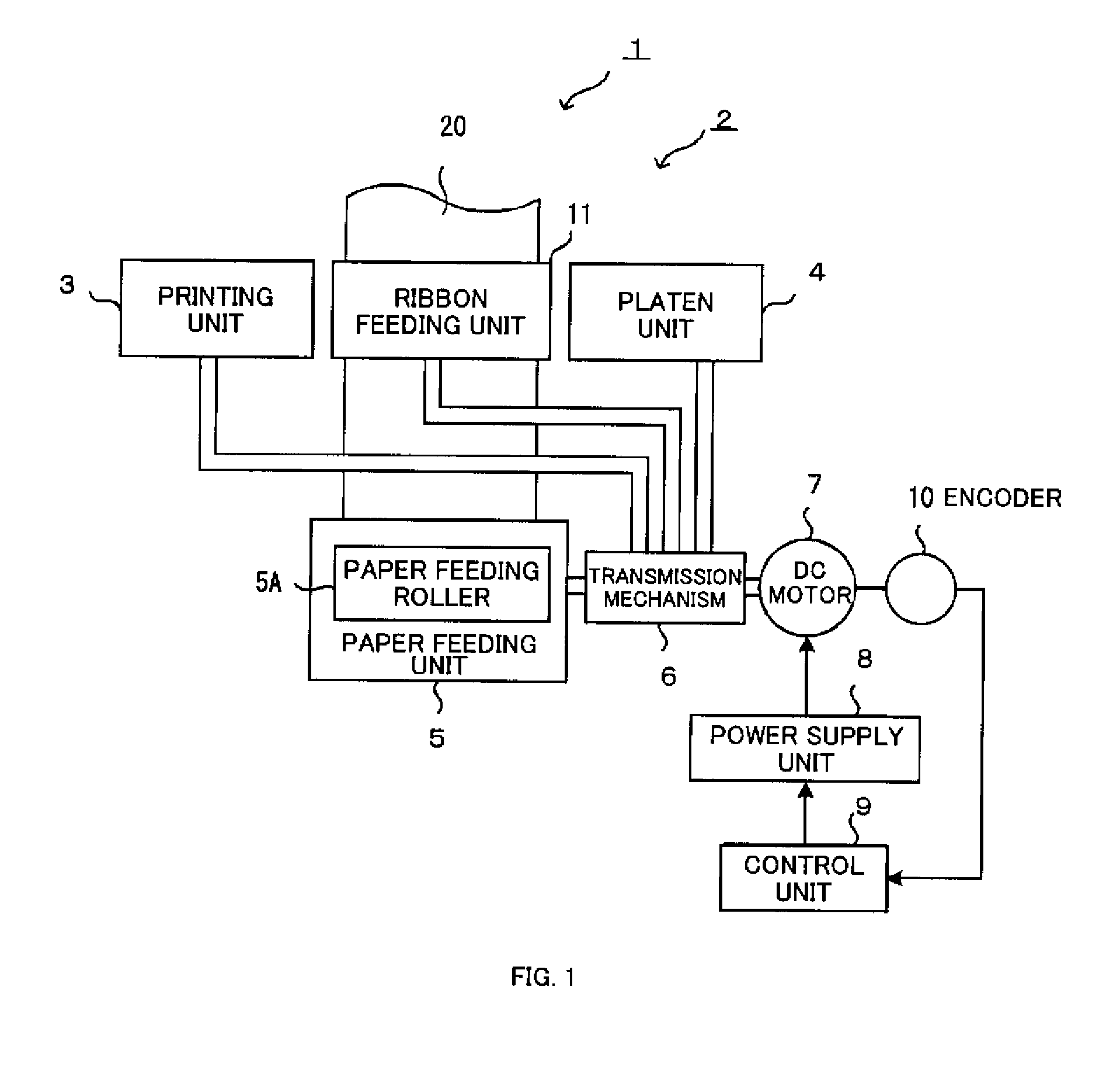
[0127]FIG. 1 is a diagram for describing the schematic structure of the present invention. In FIG. 1, a printer 1 is provided with a printing mechanism unit 2 for performing the printing, and a paper feeding unit 5 for feeding printer paper 20. The printing mechanism unit 2 is provided with a printing unit 3 that has a type roller, and the like, a platen unit 4 that presses printer paper 20 against the type roller, with an ink ribbon (not shown) interposed therebetween, and a ribbon feeding unit 11 for feeding and ink ribbon between the printing units and the printer paper. The paper feeding unit 5 is provided with a paper feeding roller 5A, where this paper feeding roller 5A is driven rotationally by a DC motor 7 through a transmission mechanism 6 comprising gears, and the like. The printing unit 3, platen unit 4, and ribbon feedi...


PUM


Abstract

In speed control that is performed within a single operating cycle of a printer, three-level control of ON control, OFF control, and chopper control, is performed in place of the two-level control of ON control and OFF control, to effectively suppress speed variations due to load variations within a single operating cycle, even in small printers provided with DC motors having small output torques. In a printer comprising a DC motor 7, a paper feeding unit 5 that includes a paper feeding roller that uses the DC motor as the driving source, and a printing mechanism unit 2, for printing, in use of the printing mechanism unit 2, onto paper that is advanced by a specific amount by the paper feeding unit 5, an encoder 10 for outputting pulse signals according to the rotation of the DC motor 7 is provided. The encoder 10 is provided with a pulse forming region for forming a pulsed signal, on the periphery of an encoder plate, where this pulse forming region is provided with a non-uniform spacing region in a section within a uniform spacing region.

Description

TECHNICAL FIELD[0001]The present invention relates to a printer and to a DC motor speed control device used in the printer.BACKGROUND ART[0002]A variety of printers are known as output devices for data processing devices and the like. DC motors that are suitable for small printers are used as the driving source for driving these printers. These printers have structures provided with a paper feeding unit for feeding the printer paper, a printing unit for printing characters onto the printer paper, and a printing mechanism unit that includes a ribbon feeding unit for feeding a ribbon between the printing unit and the printer paper, where the paper feeding unit and the printer mechanism unit are driven by a single DC motor.[0003]Typically, in a printer it is desirable to minimize the difference in speed between the printing speed of the printing mechanism unit and the paper feed speed of the paper feeding unit in order to reduce the printing misalignment. For example, if the paper feed...

Claims


Application Information

Patent Timeline
Patent Type & Authority Patents(United States)
IPC IPC(8): B41J11/42B41J29/38H02P7/06H02P7/29
CPCB41J13/0027H02P7/29H02P2203/09
Inventor TSUGARU, HIROYUKIMATSUSHIMA, GEN
Owner CITIZEN WATCH CO LTD
Why Eureka
Try Eureka