
Qualification system and method for chilled water plant operations

a technology for a chilled water plant and a validation system, applied in the direction of process and machine control, instruments, computer control, etc., can solve the problems of large energy consumption of building systems, industrial machinery, other equipment, and other equipment to produce an output, and achieve the effect of reducing the data set, accurate determination, and reducing the number of data sets

Active Publication Date: 2013-04-09
SIEMENS IND INC
View PDF46 Cites 31 Cited by
  • Summary
  • Abstract
  • Description
  • Claims
  • Application Information

AI Technical Summary

Benefits of technology

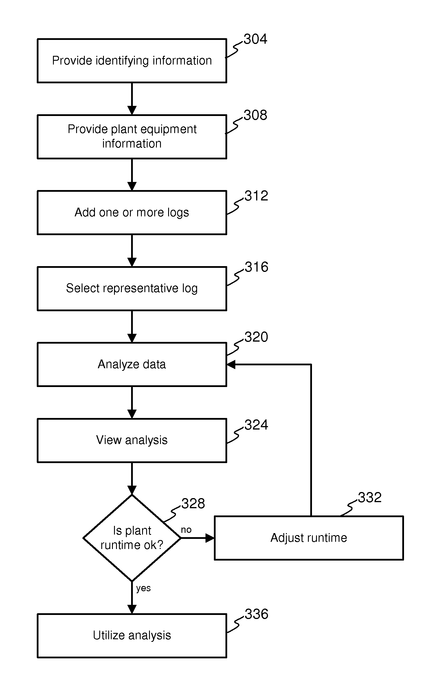
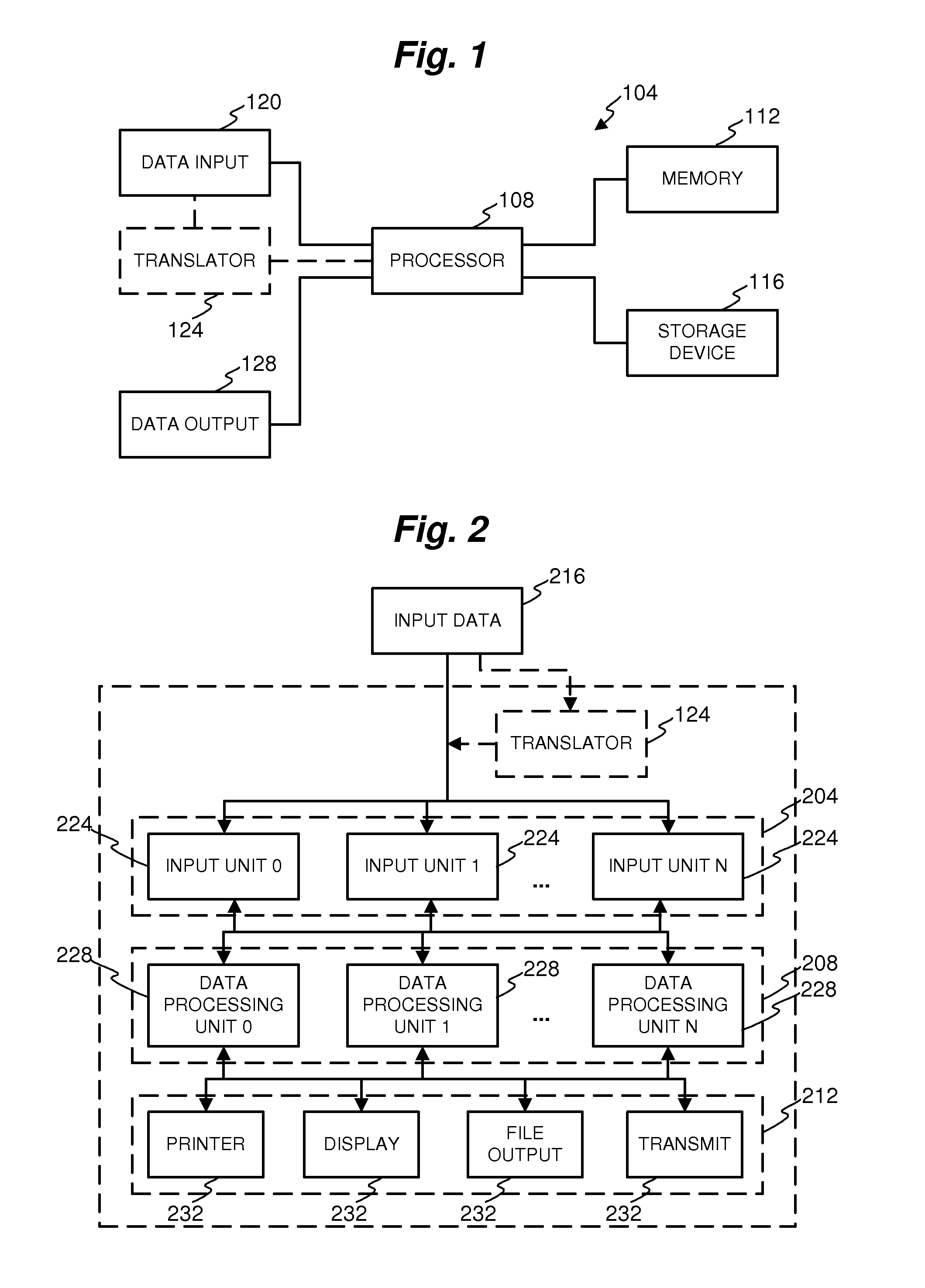
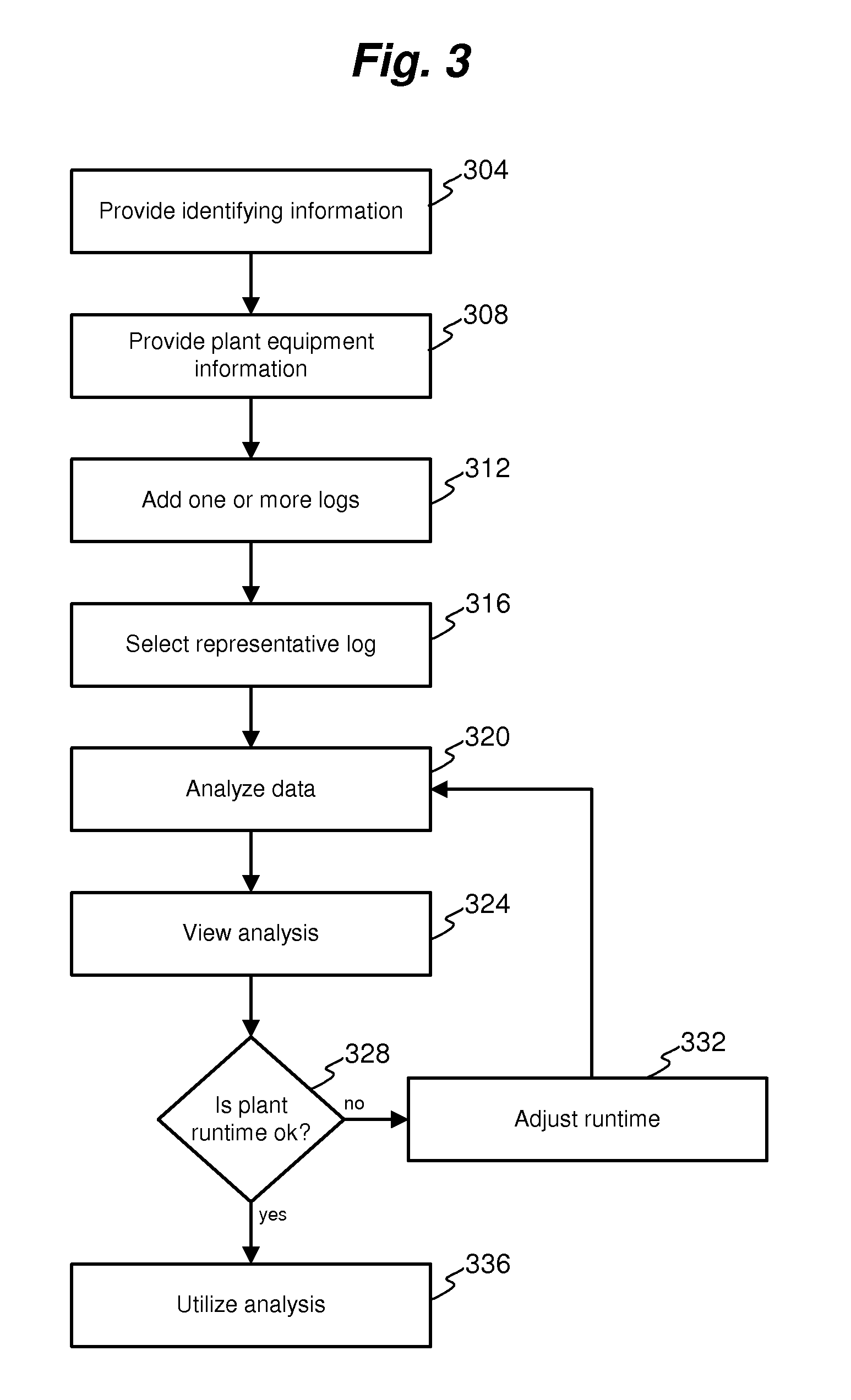
[0008]A qualification system for determining the effect(s) of one or more chilled water plant upgrades is disclosed herein. The qualification system allows the effect of upgrades to be accurately determined. In one or more embodiments, the qualification system is capable of producing an accurate representation of the effect of upgrades using a reduced data set. This allows the effect of upgrades to be determined very quickly and efficiently. In addition, the qualification system may utilize various types and amounts of actual chilled water plant log data and characteristics to produce an accurate analysis for a particular chilled water plant. The qualification system may accept additional log data to reduce margins of error as desired in one or more embodiments.
[0021]One or more results of the analysis may be presented to display the effect of the one or more chilled water plant upgrades. In addition, additional representative log data may be identified and inputted to increase the accuracy of the analysis. A geographic location of the chilled water plant may be inputted into the one or more data inputs to allow the idealized power utilization to be determined with wet bulb data for the geographic location.

Problems solved by technology

Building systems, industrial machinery, and other equipment consume energy to produce an output.
Such equipment typically utilizes a substantial amount of energy due to its scale.
Accordingly, the cost of operating such equipment is substantial.
However, this typically occurs at great cost.

Method used


Image

  • Qualification system and method for chilled water plant operations
  • Qualification system and method for chilled water plant operations
  • Qualification system and method for chilled water plant operations

Examples


Embodiment Construction

[0040]In the following description, numerous specific details are set forth in order to provide a more thorough description of the present invention. It will be apparent, however, to one skilled in the art, that the present invention may be practiced without these specific details. In other instances, well-known features have not been described in detail so as not to obscure the invention.

[0041]Industrial and commercial equipment systems typically comprise multiple pieces of complex machinery or devices that work in conjunction to produce a desired output. In the case of a chilled water plant for example, the output may be chilled water used to cool the air of a building, campus, or other area. Because these systems are complex and include multiple pieces of machinery, it is extremely difficult to assess their energy utilization, efficiency, effectiveness, or a combination thereof without taking direct measurements from the systems.

[0042]Likewise, the effect of potential upgrades of...


PUM


Abstract

A qualification system for determining the effects of one or more upgrades or modifications to a chilled water plant is disclosed herein. The qualification system my collect various data from operating logs of a chilled water plant. The data may be collected in stages, where at least one first stage may be used to collect data used to identify representative log data. The representative log data may then be used to perform an accurate analysis to determine the effects of one or more upgrades or modifications. In this manner, the qualification system provides accurate analysis while reducing data entry. In addition, the qualification system may accept varying amounts of data such as to reduce percentage error or the like in its analysis.

Description

CROSS-REFERENCE TO RELATED APPLICATION[0001]This application is a continuation-in-part of U.S. patent application Ser. No. 12 / 507,806 titled Demand Flow Pumping, filed Jul. 23, 2009 now U.S. Pat. No. 8,275,483.BACKGROUND OF THE INVENTION[0002]1. Field of the Invention[0003]The invention relates to qualification and validation systems for equipment operating procedures, and particularly to a qualification system and method for chilled water plant operations.[0004]2. Related Art[0005]Building systems, industrial machinery, and other equipment consume energy to produce an output. For example, a building or campus chilled water plant utilizes electricity or other energy to produced chilled water to control the environment within the building or campus. Such equipment typically utilizes a substantial amount of energy due to its scale. Accordingly, the cost of operating such equipment is substantial. Though efforts by the equipment manufacturers and operators have reduced energy utilizati...

Claims


Application Information

Patent Timeline
Patent Type & Authority Patents(United States)
IPC IPC(8): G05D3/12G05D11/00G05D9/00G05D5/00G05D17/00
CPCG06Q10/06G06Q50/12G06Q50/08G06Q50/06G05B15/02Y02P90/82G16Z99/00
Inventor HIGGINS, ROBERT
Owner SIEMENS IND INC
Learn More