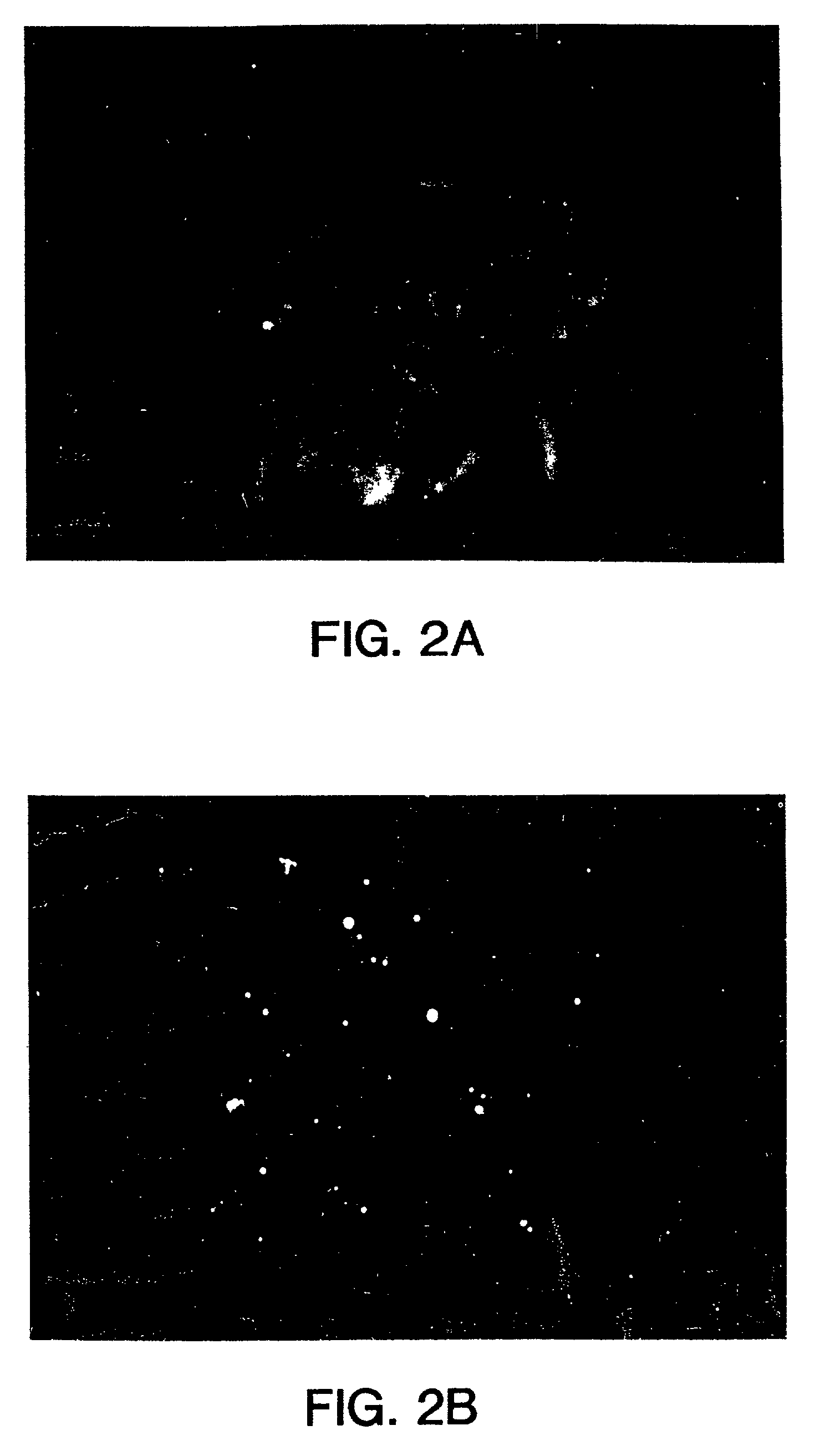
Chromosome-specific staining to detect genetic rearrangements

Inactive Publication Date: 2013-04-09
UNIVERSITY OF CHICAGO
View PDF7 Cites 0 Cited by
  • Summary
  • Abstract
  • Description
  • Claims
  • Application Information

AI Technical Summary

Benefits of technology

This patent describes methods for detecting chromosomal abnormalities, specifically genetic rearrangements, using a staining technique that can predict the response of a patient to various therapies, such as chemotherapy and surgery. The invention also provides automated analysis using computer assistance and high complexity nucleic acid probes for rapid and efficient detection of these abnormalities. This technology has direct application in genetic screening, cancer diagnosis, and biological dosimetry.

Problems solved by technology

Such nucleic acid probes useful for the detection of genetic rearrangements are typically of high complexity.

Method used


Image

  • Chromosome-specific staining to detect genetic rearrangements
  • Chromosome-specific staining to detect genetic rearrangements
  • Chromosome-specific staining to detect genetic rearrangements

Examples


case i

[0242]

[0243]The complexity of the probe is about 50 kb to about 100 kb. (In this case the complexity may be approximately equal to L since the probability is that no repetitive sequences will typically occur with more than a few copies in such a number of bases). Using a standard hybridization mixture (as exemplified in Section VI.B, infra), the target can be hybridized with about 2 ng of labeled probe DNA in 10 ul of hybridization mix, corresponding to approximately 1 pg / ul per kb of specific sequences (as used in Section VI.B, infra). Suppose the hybridization is to a slide containing 104 cells (a typical number), and each cell has about 6 pg of DNA, (typical for mammals). Then in this model calculation, there is 3 pg of shared repetitive sequences per cell. Thus, for 104 cells there are 3×10⁴ pg or 30 ng of shared sequences on the slide. Similarly, there is 104×0.5×105×6 / 3×10⁹ pg=1 pg of target for the specific sequences. The probe contains 1 / 2×2 ng or 1 ng of shared sequences an...

case ii

[0245]

[0246]As the size of the target region is increased, the complexity of the probe necessarily is increased, and the amount of DNA in the hybridization mix needs to be increased in order to have a sufficient concentration of each portion of specific sequence to hybridize. Also, if one desires to decrease the hybridization time of the procedure, the probe concentration must be increased. In these situations, the increase in probe concentration results in an increase in the amount of shared sequences in the hybridization mixture, which in turn increases the amount of hybridization that will occur to the shared sequences in the target area or areas, thereby reducing the contrast ratio.

[0247]With very high complexity probes spanning several entire chromosomes, L / G can approach 1. In order to stain such a portion of the genome within a reasonable time, for example, overnight, the concentration of labeled nucleic acid needs to be increased, for example, 200 ng in 10 ul of hybridizatio...


PUM

PropertyMeasurementUnit
Digital informationaaaaaaaaaa

Abstract

Methods and compositions for staining based upon nucleic acid sequence that employ nucleic acid probes are provided. Said methods produce staining patterns that can be tailored for specific cytogenetic analyzes. Said probes are appropriate for in situ hybridization and stain both interphase and metaphase chromosomal material with reliable signals. The nucleic acid probes are typically of a complexity greater than 50 kb, the complexity depending upon the cytogenetic application. Methods and reagents are provided for the detection of genetic rearrangements. Probes and test kits are provided for use in detecting genetic rearrangements, particularly for use in tumor cytogenetics, in the detection of disease related loci, specifically cancer, such as chronic myelogenous leukemia (CML) and for biological dosimetry. Methods and reagents are described for cytogenetic research, for the differentiation of cytogenetically similar but genetically different diseases, and for many prognostic and diagnostic applications.

Description

RELATED APPLICATION[0001]This application is a continuation-in-part of U.S. Ser. No. 497,098, filed Mar. 20, 1989, which is a continuation-in-part of U.S. Ser. No. 444,669, filed Dec. 1, 1989, which is a continuation-in-part of U.S. Ser. No. 937,793, filed Dec. 4, 1986, which is, in turn, a continuation in part of U.S. Ser. No. 819,314, filed Jan. 16, 1986, now abandoned, of which U.S. Ser. No. 382,094, filed Jul. 19, 1989, is a continuation, by the named inventors hereof and assigned to the same assignee and claims priority in said prior filed applications.[0002]The United States Government has rights in this invention pursuant to Contract No. W-7405-ENG-48 between the U.S. Department of Energy and the University of California, for the operation of Lawrence Livermore National Laboratory.FIELD OF THE INVENTION[0003]The invention relates generally to the field of cytogenetics, and more particularly, to the field of molecular cytogenetics. The invention concerns methods for identifyin...

Claims


Application Information

Patent Timeline
IPC IPC(8): C12N15/32C12N5/071C12Q1/68
CPCC12Q1/6811C12Q1/6827C12Q1/6841C12Q1/6853C12Q1/6879C12Q1/6886C12Q2600/156C12Q2563/131C12Q2563/107C12Q2525/151
Inventor GRAY, JOE W.PINKEL, DANIELTKACHUK, DOUGLASWESTBROOK, CAROL
Owner UNIVERSITY OF CHICAGO
Why Eureka
Try Eureka