
Hydraulic upper link with float position

a technology of float position and upper link, which is applied in the field of hydraulic upper link, can solve the problems of reducing affecting the service life of the upper link, and requiring manual operation, so as to avoid excessive pivot movement between the attached implement and the utility vehicl

Inactive Publication Date: 2013-04-02
AGCO GMBH
View PDF20 Cites 6 Cited by
  • Summary
  • Abstract
  • Description
  • Claims
  • Application Information

AI Technical Summary

Benefits of technology

Enables seamless switching between rigid coupling and upper link float position without dismounting the implement, allowing for precise and rapid adjustments from the vehicle seat, enhancing operational efficiency and reducing manual labor, while providing adjustable pivot movement to accommodate varying terrain conditions.

Problems solved by technology

Another disadvantage of mechanical adjustment is the susceptibility, in particular of the partially exposed adjustment thread, to contamination due to whirled up dust and thrown up earth.
Even if the rear-mounted implement is raised from the utility vehicle, it may happen that due to bumps the rear-mounted implement makes contact with the ground and as a result is raised still further.
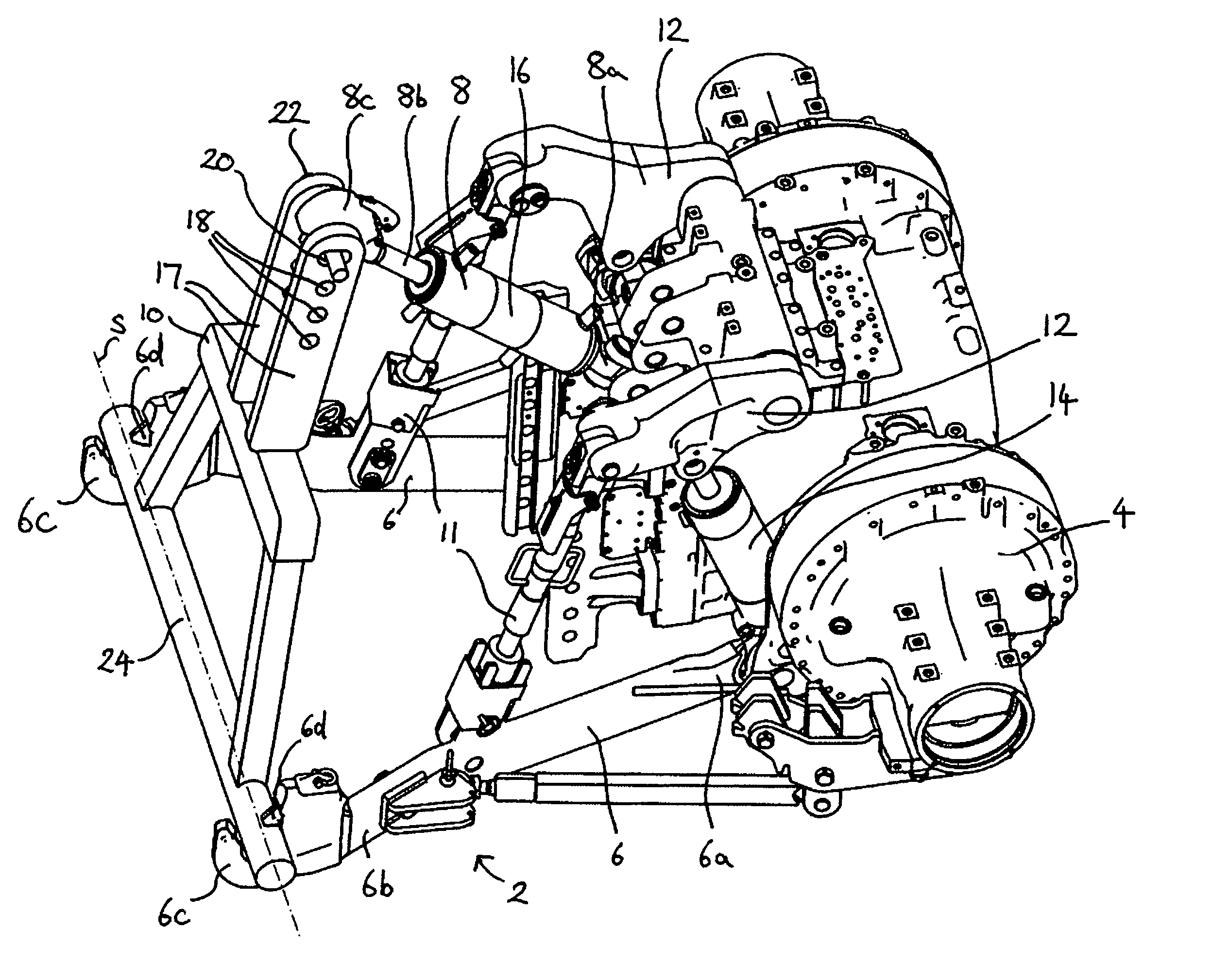
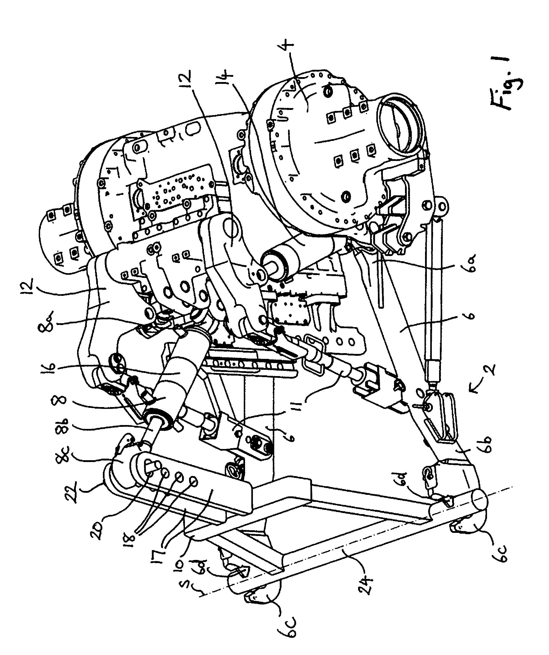
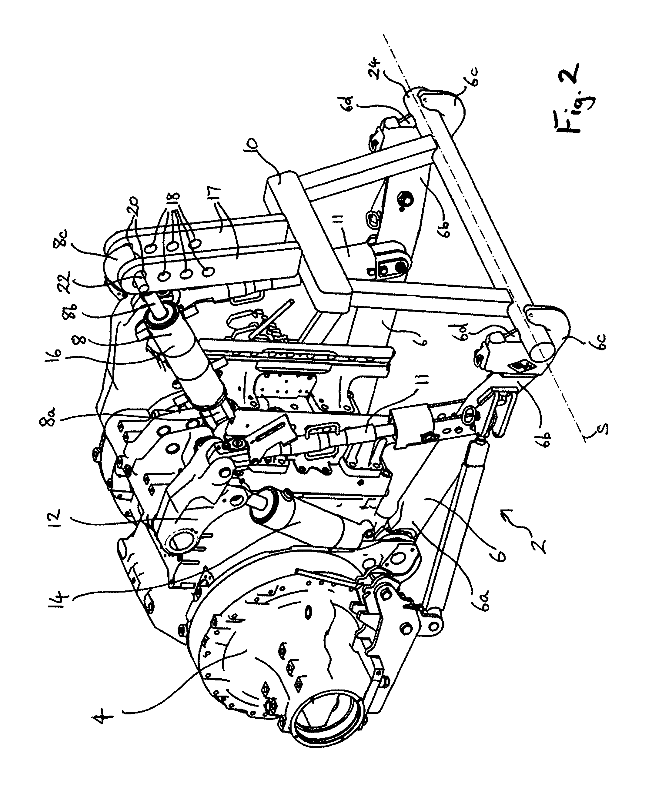
The problem with the prior art coupling of the upper link 8 to the elongated holes 20 is that this can only be done at one height.
Furthermore up until now change-over between the mode of operation with rigid coupling to the upper link and the mode of operation with upper link float position has been comparatively time-consuming and must be done by hand.

Method used


Image

  • Hydraulic upper link with float position
  • Hydraulic upper link with float position
  • Hydraulic upper link with float position

Examples


first embodiment

[0051]FIG. 5 shows a cross sectional view of an upper link 32, according to the present invention. The upper link 32 has a hydraulic cylinder 34, which can be coupled to a fluid tank 36. The hydraulic cylinder has a cylinder 38 and a piston 40, which is arranged displaceably therein, with a piston rod 42. The upper link 32 is split over its length into two, wherein a first part 44 is connected to the piston 40 by means of the piston rod 42 and a second part 46 is connected to the cylinder 38. The upper link 32 can therefore be adjusted in its length by the hydraulic cylinder 34. The hydraulic cylinder 34 is a double action cylinder, the cylinder 38 being divided by the piston 40 into a first piston chamber 48 and a second piston chamber 50.

[0052]A fluid line 52 or 54 leads away from each of the piston chambers 48, 50. By means of a 4 / 3 way valve 56 with two flow positions and a closed central position, in each case one of the piston chambers 48, 50 can be connected to a power source...

second embodiment

[0060]FIG. 6A shows an upper link 84 according to the present invention. The same reference symbols as those for the embodiment illustrated in FIG. 5 are used below for identical components. The differences compared to the embodiment illustrated in FIG. 5 are predominantly discussed in the following.

[0061]The upper link 84 again has a hydraulic cylinder 34 with a piston 40, which is displaceably arranged in a cylinder 38. The piston 40 divides the cylinder 38 into a first piston chamber 48′ and a second piston chamber 50′. In contrast to the embodiment illustrated in FIG. 5 the piston chamber 48′, in which the piston rod 42 is arranged, is designated as the first piston chamber 48′. Furthermore the piston chamber 50′, in which the piston rod 42 is not arranged, is designated as the second piston chamber 50′. As described with reference to FIG. 5, the piston 40 is actively moved by connecting one of the piston chambers 48′, 50′ to a hydraulic pump 58. In contrast to the first embodim...


PUM


Abstract

An upper link for a utility vehicle, in particular for an agricultural tractor having a hydraulic cylinder (34) for adjusting the upper link (32) and at least one fluid tank (36), to which the hydraulic cylinder (34) can be coupled, so that in a coupled condition, hydraulic fluid limited to a pre-determined volume can be exchanged between the hydraulic cylinder (34) and the fluid tank (36), and so that a piston (40) of the hydraulic cylinder (34) can move in floating fashion by a distance (ls) corresponding to the pre-determined volume in the hydraulic cylinder (34). The present invention further includes a front-end as well as to a back-end three-point hitch of a utility vehicle with two pivotally connected lower links and an upper link with such a fluid tank.

Description

CROSS REFERENCE TO RELATED APPLICATION[0001]This application is based on, and claims the benefit of priority to, German application 10 2007 017 784.6, filed 16 Apr. 2007, which priority application is hereby incorporated by reference.BACKGROUND OF THE INVENTION[0002]1. Field of Invention[0003]The present invention relates to an upper link for a utility vehicle, in particular for an agricultural tractor, wherein the upper link has a hydraulic cylinder for adjusting the upper link. Furthermore the present invention relates to a back-end and a front-end three-point hitch of a utility vehicle as well as to a utility vehicle with such a back-end and / or front-end mounted upper link.[0004]2. Description of Related Art[0005]Utility vehicles, in particular agricultural utility vehicles, such as for example an agricultural tractor, on the back-end and / or front-end often have a three-point hitch for attaching equipment. Such equipment may be an agricultural implement, such as for example a plo...

Claims


Application Information

Patent Timeline
Patent Type & Authority Patents(United States)
IPC IPC(8): A01B59/06
CPCA01B59/004A01B59/068
Inventor KAPFER, JOHANNES
Owner AGCO GMBH
Learn More