A non-static fluid pressure measuring device and method of use thereof
A fluid pressure and measurement device technology, which is applied in the fields of mechanical power, force, stress, torque, mechanical efficiency or fluid pressure and work, and can solve problems such as inability to measure fluid pressure more accurately
- Summary
- Abstract
- Description
- Claims
- Application Information
AI Technical Summary
Problems solved by technology
Method used
Image
Examples
Embodiment 1
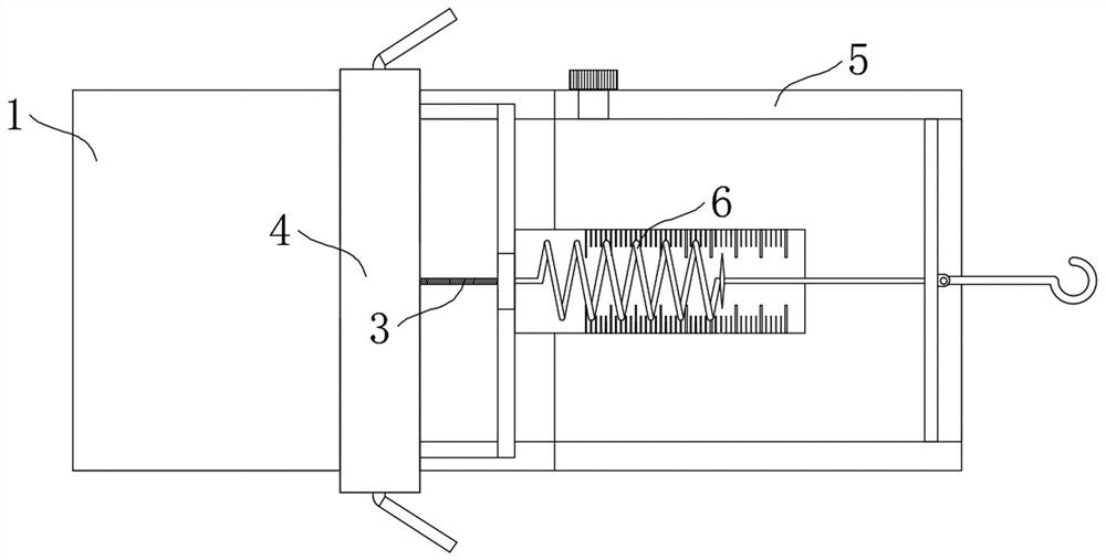
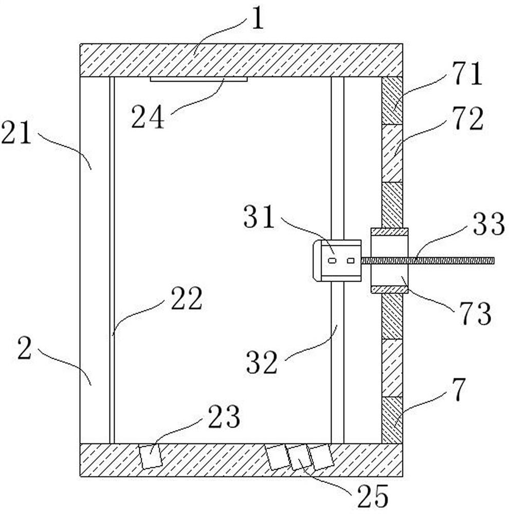
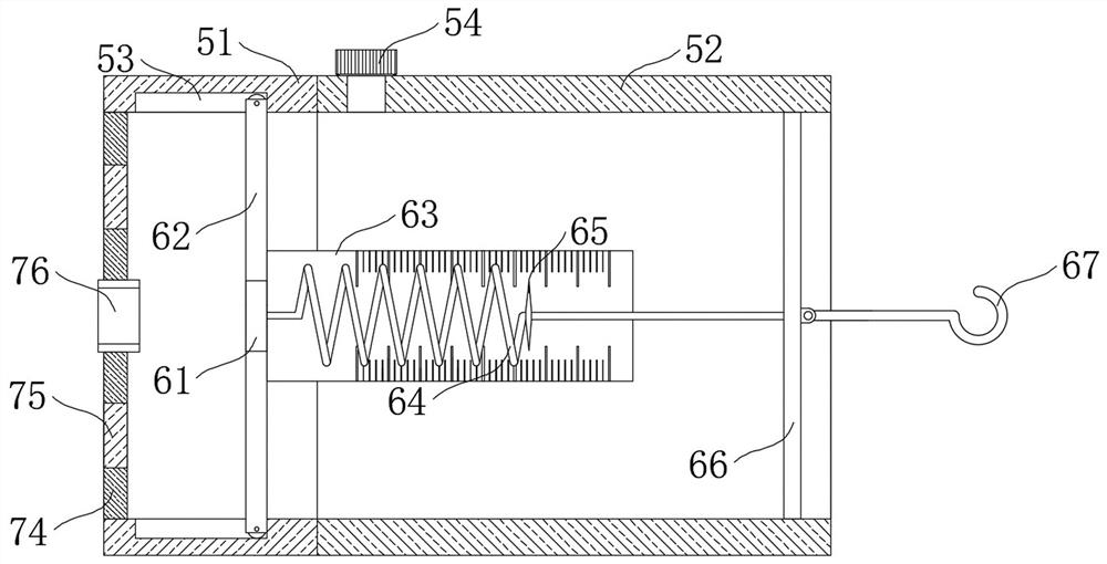
[0048] Such as figure 1 , figure 2 , image 3 , Figure 4 , Figure 5 , Figure 6 and Figure 7 As shown, this embodiment proposes a non-stationary fluid pressure measurement device, which includes a hard shell 1, and the inside of the hard shell 1 is provided with a pressure detection structure 2 and a driving mechanism 3, and the driving mechanism 3 is located on one side of the pressure detection structure 2 , the pressure detection structure 2 reflects the sensed fluid pressure through the movement of the light irradiation point, and the driving mechanism 3 operates according to the movement of the light irradiation point. One side of the hard shell 1 is provided with an observation part casing 5, and the observation part casing 5 The internal medium can be replaced according to actual needs. There is a disassembly sealing mechanism 4 between the hard casing 1 and the observation part casing 5. The disassembly sealing mechanism 4 is convenient for disassembling the h...
Embodiment 2
[0050] The scheme in embodiment 1 is further introduced below in conjunction with specific working methods, see the following description for details:
[0051] As a preferred embodiment, on the basis of the above method, further, the pressure detection structure 2 includes a thin film 21 fixedly connected to the inside of the hard shell 1 and away from the side of the drive mechanism 3, when the external pressure is greater than the internal pressure of the hard shell 1 , the thin film 21 is deformed, and the surface of the thin film 21 close to the driving mechanism 3 is coated with a reflective layer 22. When the thin film 21 is deformed, the path of the light reflected by the reflective layer 22 changes, and the inner wall of one side of the hard shell 1 is embedded with a The reflective mirror 24 reflects the light reflected by the reflective layer 22 again, and enlarges the moving distance of the light point. The other side of the hard shell 1 is embedded with a light sour...
Embodiment 3
[0061] The schemes in Embodiment 1 and Embodiment 2 are further introduced below in conjunction with specific working methods, see the following description for details:
[0062] A method for using a non-static fluid pressure measuring device, comprising the following steps:
[0063] Step 1, assemble the device: according to the actual needs, replace the observation part housing 5 and its internal structure and the internal medium of the observation part housing 5 according to the fluid pressure according to the actual needs, and the hard case 1 and the observation part can be connected by disassembling the sealing mechanism The shell 5 is separated, and the observation part shell 5 and its internal structure are replaced according to the external pressure, and then the hard shell 1 and the replaced observation part shell 5 are quickly assembled by the assembly mechanism 7;
[0064] Step 2, pressure detection: during detection, the outside of the hard shell 1 is in the fluid, ...
PUM
 Abstract
Description
Claims
Application Information
 - Generate Ideas
- Intellectual Property
- Life Sciences
- Materials
- Tech Scout
- Unparalleled Data Quality
- Higher Quality Content
- 60% Fewer Hallucinations
Browse by: Latest US Patents, China's latest patents, Technical Efficacy Thesaurus, Application Domain, Technology Topic, Popular Technical Reports.
© 2025 PatSnap. All rights reserved.Legal|Privacy policy|Modern Slavery Act Transparency Statement|Sitemap|About US| Contact US: help@patsnap.com


