
Gripper device for a bag filling and packaging machine

a bag filling and packaging machine technology, applied in the field of grippers, can solve the problems of low rigidity (strength), inability to open the bag mouth into the optimal shape, and complicated work, and achieve the effect of easy adjustmen

Active Publication Date: 2020-10-13
TOYO JIDOKI CO LTD
View PDF13 Cites 0 Cited by
  • Summary
  • Abstract
  • Description
  • Claims
  • Application Information

AI Technical Summary

Benefits of technology

The present invention provides an improvement to a gripper device used in a bag filling and packaging machine. The device can easily adjust the reference spacing between gripper arms when the width of bags changes, and can also easily adjust the movement distance of the gripper arms when opening and closing the bags. The structural design of the device ensures that it can handle changes in bag orientation and can package heavy content. Additionally, the device provides a gripper arm pivot mechanism that pivots the gripper arms in symmetrical motion, which enables easy adjustment of the reference spacing and movement distance for all the gripper devices.

Problems solved by technology

It is also necessary to perform this adjustment work for all of the sets of gripper arms installed in the bag filling and packaging machine, which makes the work more complicated.
Therefore, such a problem occurs that when the bag width or the type of contents is changed, the bag mouth cannot be opened into the optimal shape for the bag width or for the kind of contents to be filled (for example, it may occur that the bag mouth is not opened in a large circular shape or in an elongated elliptical shape).
The clamps have to be formed by relatively small parts, which are low in rigidity (strength) and have poor durability, and are prone to looseness brought about by wear of the rotating parts (the main pins (43)) and the like, making this configuration unsuitable to packaging heavy contents.
In addition, although Patent Document 3 discloses the opening and closing of pair of gripper arms, it does not disclose anything about adjustment of the reference spacing between a pair of (or two) gripper arms to accommodate bags of different widths.

Method used


Image

  • Gripper device for a bag filling and packaging machine
  • Gripper device for a bag filling and packaging machine
  • Gripper device for a bag filling and packaging machine

Examples


Embodiment Construction

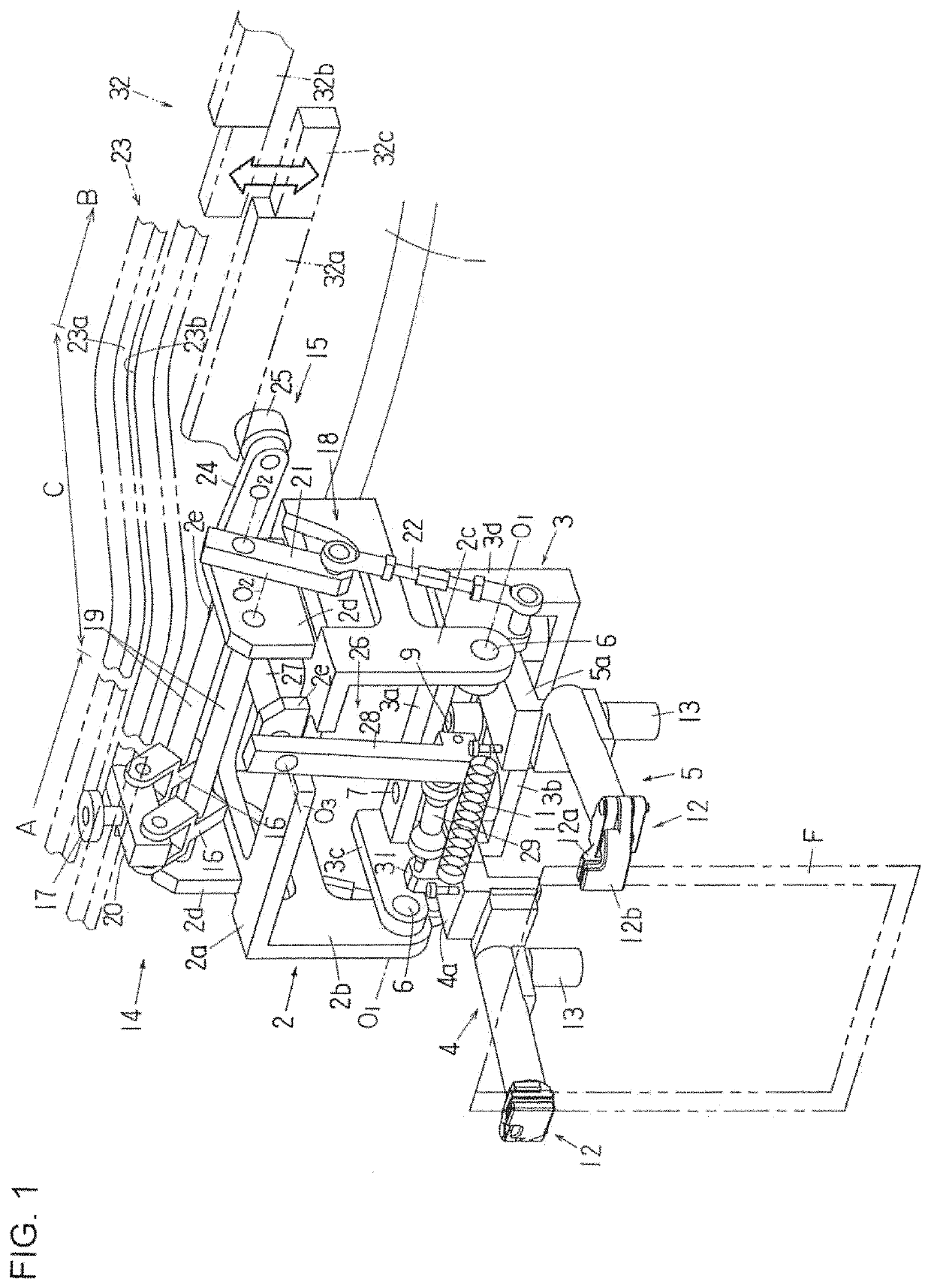
[0031]In a bag filling and packaging machine, particularly in a rotary bag filling and packaging machine, a plurality of gripper devices are provided at equidistant spacing on the circumference of a circular table that rotates continuously or intermittently. As the table rotates intermittently, the gripper devices are moved intermittently along a predetermined circular path, bags are supplied to the gripper devices one by one in the course of this intermittent movement and held by the gripper devices, and then the bags held by the gripper devices are subjected to various kinds of packaging processing, including opening of the bag mouth, filling of the bag with its contents, sealing of the bag mouth, and so forth.

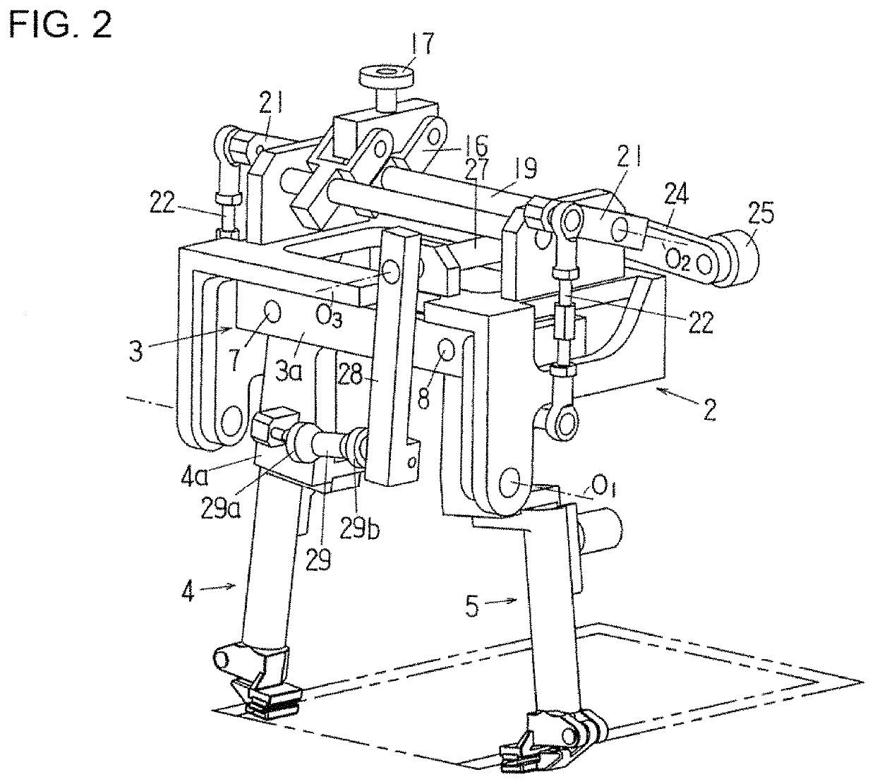
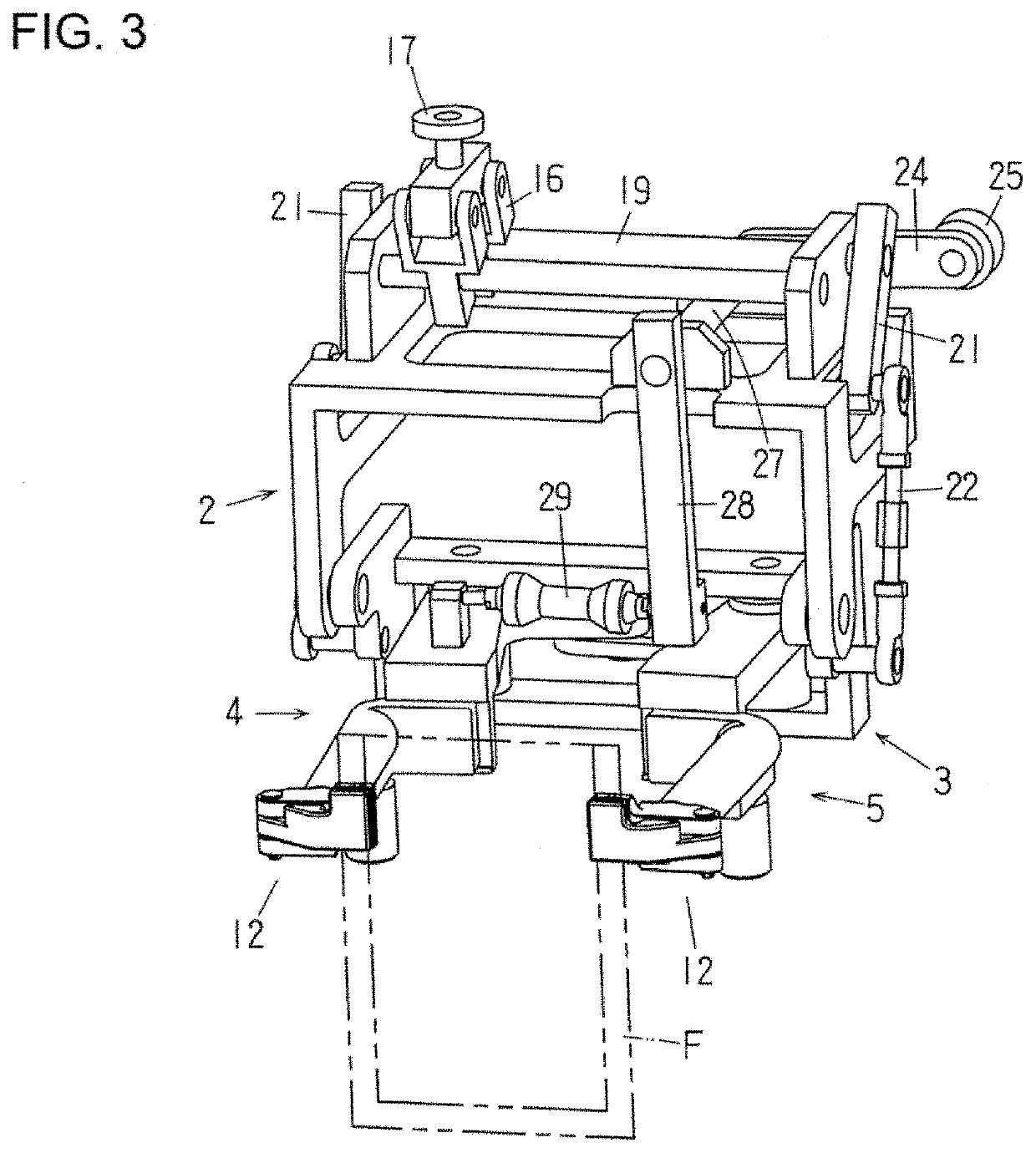
[0032]A case in which the gripper device according to the present invention is provided in an intermittently rotating rotary bag filling and packaging machine will be described below concretely with reference to FIGS. 1 to 6. In this rotary bag filling and packaging machine,...


PUM


Abstract

A gripper device used in a bag filling and packaging machine and moved, while holding a bag, along a predetermined path to change the orientation of the bag, the gripper device including: a movable frame that is moved along the predetermined path in a horizontal plane, a pivot frame that is pivotably supported by the movable frame and has a horizontal pivot axis, a pair of gripper arms that are pivotably supported by the pivot frame and pivoted, in conjunction with each other, symmetrically in a plane parallel to the pivot axis of the pivot frame, a bag orientation changing mechanism that is installed on the movable frame and pivots the pivot frame at an angle of 90°, and a gripper arm pivot mechanism that is installed on the movable frame and pivots the pair of gripper arms.

Description

BACKGROUND OF THE INVENTION1. Field of the Invention[0001]The present invention relates to a gripper device which are provided in a plurality of numbers in a bag filling and packaging machine and moved, while holding the side edges of a bag, along a predetermined path and more particularly to a gripper device which, in the course of moving, changes a bag from a vertical orientation to a horizontal orientation or from a horizontal orientation to a vertical orientation.2. Description of the Related Art[0002]Patent Documents 1 to 3 discloses such gripper devices as described above,[0003]The gripper devices disclosed in Japanese Patent Application Publication (Kokoku) Nos. H7-2490 (called “Patent Document 1”) and H6-102451 (called “Patent Document 2”) includes (the numbers and letters in parentheses below are those given in Patent Document 1) a movable plate (3) fixed to a timing belt (2), a shaft member (5) rotatably installed on the moving plate (3), holding pieces (7) fixed to the sh...

Claims


Application Information

Patent Timeline
Patent Type & Authority Patents(United States)
IPC IPC(8): B65B43/62B65B43/46B65B43/32B65B59/00B65B43/16B65B43/30
CPCB65B43/465B65B59/005B65B43/32B65B43/62B65B43/30B65B59/003B65B43/16B65B43/60B65B65/02F16H25/08
Inventor YOSHIKANE, TOHRU
Owner TOYO JIDOKI CO LTD
Learn More