Cap for a spill-proof beverage container

a beverage container and cap technology, applied in the field of cap for a spill-proof beverage container, can solve the problem of difficult (if not impossible) sealing, and achieve the effect of reliable sealing

Active Publication Date: 2013-03-26
SAMSON
View PDF15 Cites 10 Cited by
  • Summary
  • Abstract
  • Description
  • Claims
  • Application Information

AI Technical Summary

Benefits of technology

[0056]It should be made clear that the invention is not restricted to use in a cup and may be used as a bottle cap or even with flexible walled containers. Furthermore, the cap need not be separable from the container may be permanently built into it, allowing the entire container to be disposable. Further, the spout part could be flexible and have an elongated extension such as a straw.

Problems solved by technology

In practice, such a seal is difficult (if not impossible) to achieve, especially in a valve that is designed to be taken apart and reassembled for cleaning.

Method used


Image

  • Cap for a spill-proof beverage container
  • Cap for a spill-proof beverage container

Examples


Embodiment Construction

)

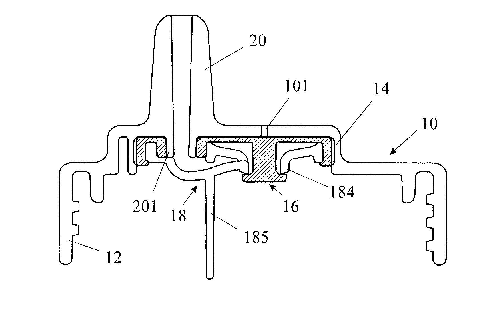
[0029]Throughout the description, when referring to directions such as downwardly, it is assumed that the cup is in the position shown in FIG. 1 in which the base of the cup is resting on a horizontal surface and the cap is uppermost.

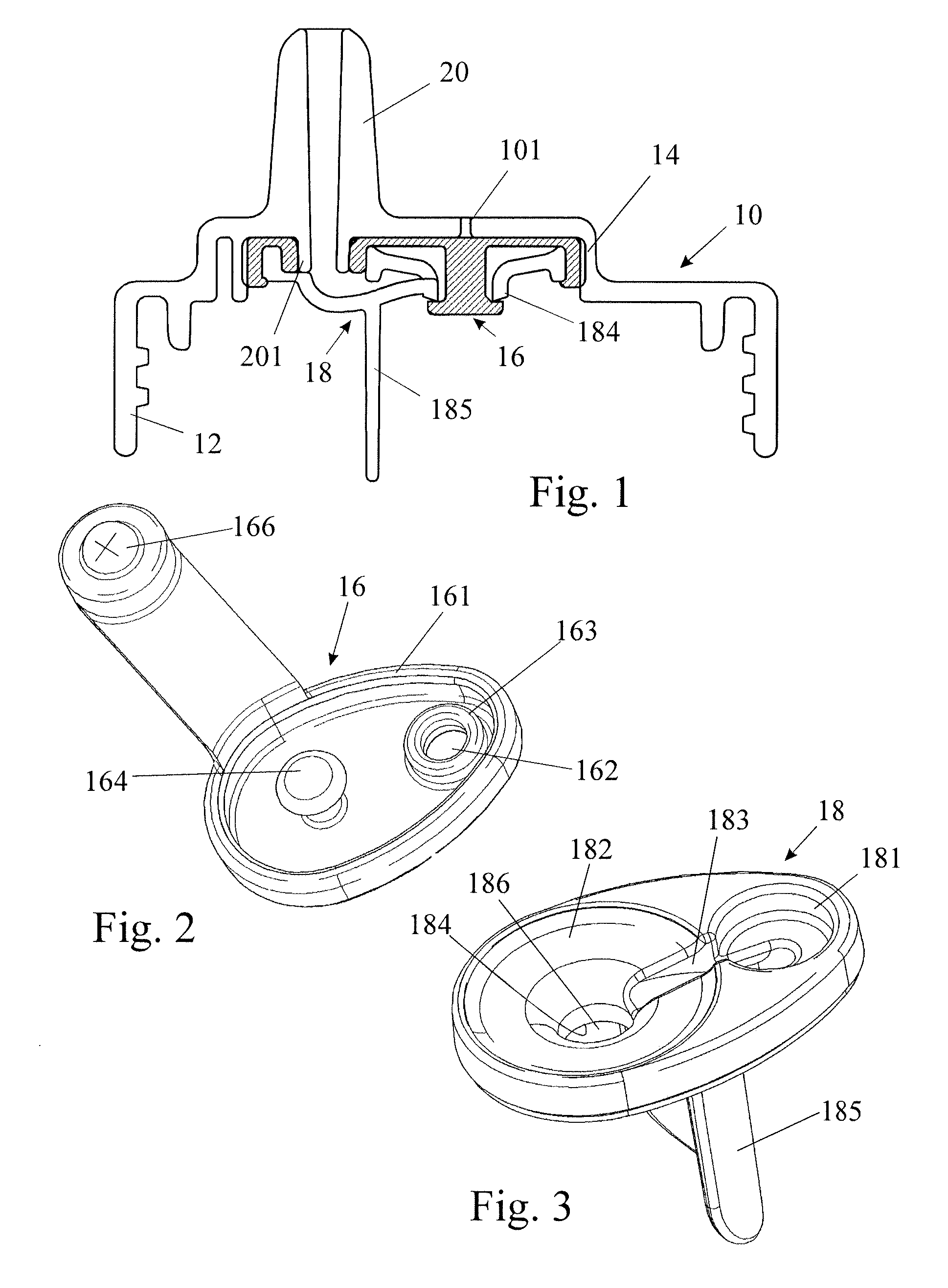
[0030]FIG. 1 shows only the cap 10 of a spill-proof drinking cup having an internally threaded rim 12 so that it may be screwed onto the cup (not shown). The cap incorporates an oval recess 14 for receiving two members 16 and 18 which constitute a demand valve. A spout 20, formed preferably integrally with the cap 10, opens into the recess 14.

[0031]The member 16 is made of a resilient material while the member 18 and the cap 10 are rigid, although they might contain soft or resilient sections. To allow the three components 10, 16 and 18 to be readily distinguished from one another, only the resilient member 16 has been cross hatched in the section of FIG. 1. The three components of the valve are separable from one another, so that they may be cleaned, ...


PUM


Abstract

A cap is described for closing a liquid beverage container for allowing the beverage to be sucked out of the container through a spout, while preventing spillage when no suction takes place. A demand valve is incorporated into the cap, which has an inlet port communicating with the interior of the container, a discharge port communicating with the spout and a control port communicating with the ambient atmosphere through a hole in the cap. The valve has a valve seat and a closure element controlling the flow from the inlet port to the discharge port urged to move into an opening position in dependence on the excess of the control pressures over that in the discharge ports, this movement being in the direction opposed to the flow and urged by the pressure in the container in a direction to seal against the valve seat. In the invention, the demand valve is formed by two members that are mounted on the inner surface of the cap. The first member is rigid and defines the valve inlet port and the valve seat. The second member incorporates the valve closure element and a resilient membrane which includes the valve closure element and serves as a pressure sensitive diaphragm. The second member also seals against the first member, around the hole in the cap and around the spout.

Description

[0001]This Application is a national phase of, and claims priority from, PCT Application No. PCT / GB2008 / 050249, filed on Apr. 9, 2008, which claims priority from United Kingdom Application No. GB 0707156.6, filed on Apr. 13 2007, all of which are hereby incorporated by reference as if fully set forth herein.FIELD OF THE INVENTION[0002]The present invention relates to a cap for a spill-proof beverage container and to such a cap when fitted releasable or permanently to a beverage container.BACKGROUND OF THE INVENTION[0003]The need for spill-proof cups, as used by infants and the infirm, is well known. These cups are liquid-tight, preferably also air-tight, and are designed not to leak when the cup is held in a tilted or overturned position by a child, or when the cup falls on its side or even turns over. Preferably, the cup should also resist spillage when shaken or swung, as happens when children carry it around carelessly.[0004]There are various known designs serving this purpose. A...

Claims


Application Information

Patent Timeline
Patent Type & Authority Patents(United States)
IPC IPC(8): B65D51/16
CPCB65D47/2062A47G19/2272A47G19/22A47G19/2266B65D47/00B65D47/04B65D47/06B65D47/32B65D47/20
Inventor SAMSON
Owner SAMSON
Why Eureka
Try Eureka