
Protective ballistic shield

a ballistic shield and shield technology, applied in shields, protective equipment, weapons, etc., can solve the problems of limiting the visibility of users, affecting the protection of users, and many casualties being hit in areas not protected by body armor or helmets

Active Publication Date: 2013-03-26
UNITED STATES OF AMERICA THE AS REPRESENTED BY THE SEC OF THE ARMY
View PDF7 Cites 12 Cited by
  • Summary
  • Abstract
  • Description
  • Claims
  • Application Information

AI Technical Summary

Benefits of technology

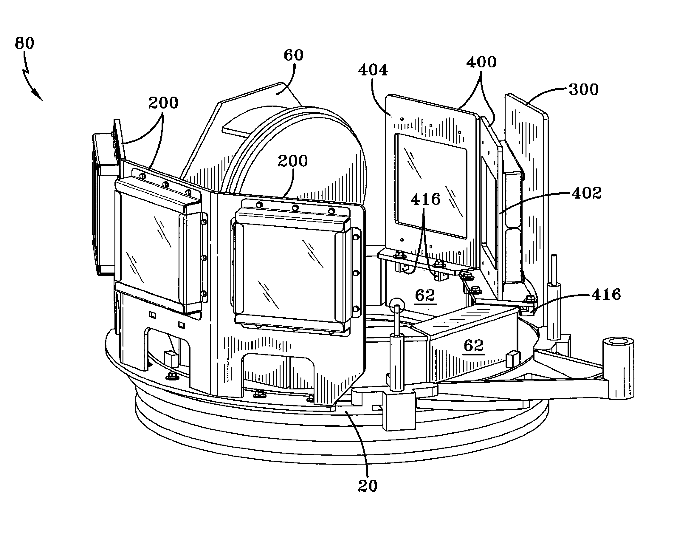
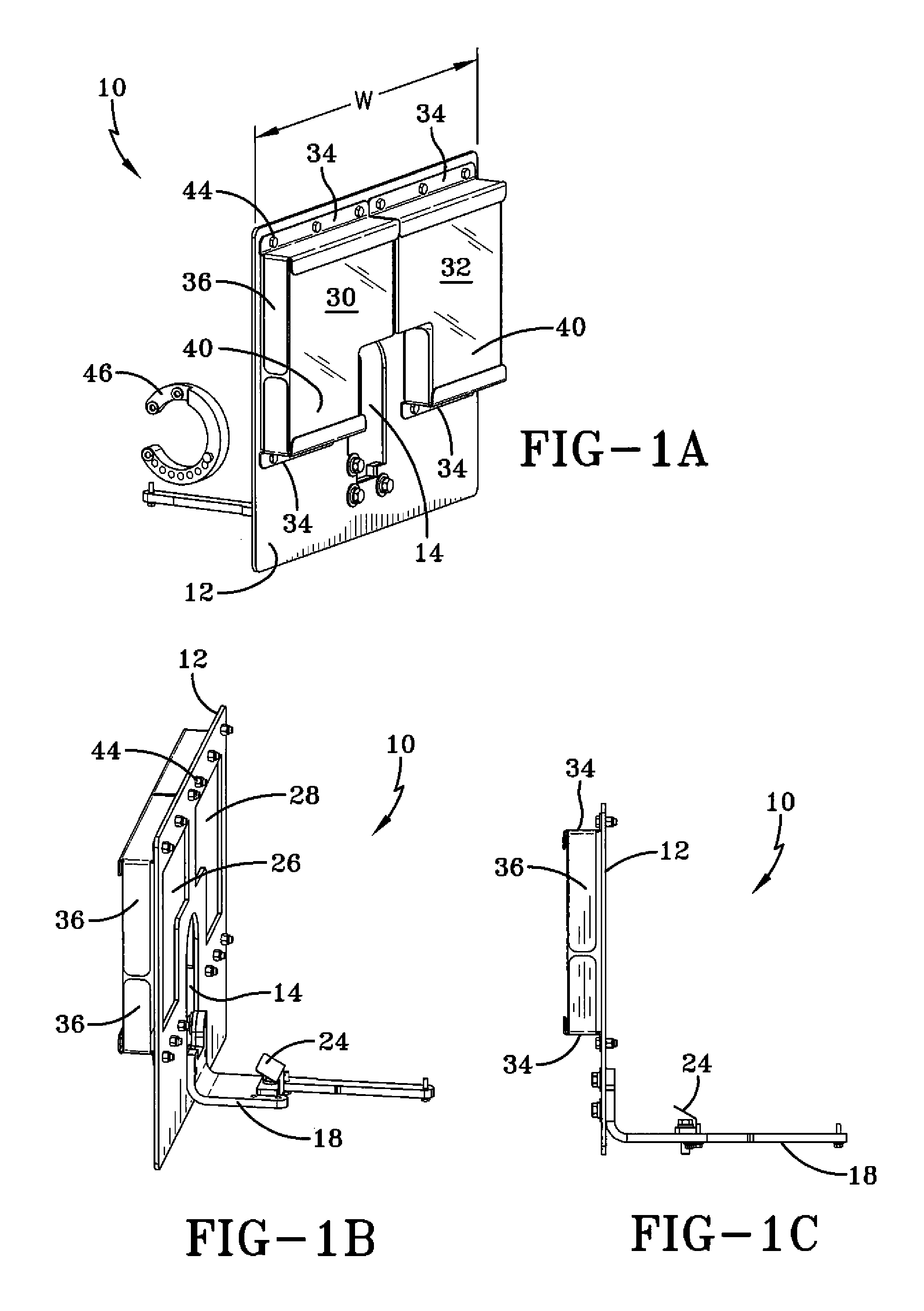
The invention provides a protective shield for a tank commander's station. The shield includes a front plate, a weapon barrel opening, and at least one window opening. The window opening has transparent ballistic protection and is fixed to the front plate using Z-shaped brackets. The shield also includes a rotating outboard shield, a rotating inboard shield, and a stationary inboard shield. The rotating inboard shield is located within the rotation of the rotating outboard shield and has an arcuate base with a tab opening. The stationary inboard shield has separate front and rear shields with window openings and a base with a tab opening. The armor kit also includes the weapon shield, rotating outboard shield, rotating inboard shield, and stationary inboard shield. The technical effects of the invention include improved protection for the tank commander's station and increased ability to see and respond to threats.

Problems solved by technology

The weapon fire presents a grave risk to soldiers who may be exposed when firing at the enemy.
In particular, many casualties are hit in areas not protected by body armor or helmets, such as the neck or face.
A disadvantage of gun shields may be that they limit the visibility of the user.
In the case of vehicle-mounted guns, gun shields may also adversely affect the performance of tasks other than firing a gun.
When using the .50 caliber machine gun, the tank commander may be vulnerable to enemy fire.

Method used


Image

  • Protective ballistic shield
  • Protective ballistic shield
  • Protective ballistic shield

Examples


Embodiment Construction

[0036]Protective ballistic shields may provide cover, concealment and ballistic protection. The present invention may be used wherever ballistic protection may be needed. The disclosed embodiments may be useful, for example, for the operator of the M1A2 Abrams tank commander's weapon station. The shields may include shields mounted on the outboard and inboard side of the commander's weapon station. The shields may include stationary shields and rotating shields. Some shields may be fixed in place by bolting to pre-existing bolt holes on the commander's rotating weapon ring. Other shields may be fixed by clamping on the top of periscope blocks.

[0037]A front shield for the commander's weapon station may include a mounting bracket that clamps to the existing weapon cradle. A deflecting plate may deflect ammunition casings that have been ejected from the commander's weapon away from the mounting bracket. A ring tensioner may apply a load to the spring in the weapon cradle to offset the ...


PUM


Abstract

An armor kit may include a weapon shield having a front plate with a weapon barrel opening and at least one window opening; a rotating outboard shield including a front panel connected to a center panel and a rear panel connected to the center panel, each of the front, center, and rear panels including a window opening and a window disposed over the window opening; a rotating inboard shield having an upper portion that is solid and a lower portion with a viewing aperture, the rotating inboard shield being located generally opposite the rotating outboard shield, the rotating inboard shield and the rotating outboard shield being simultaneously rotatable and maintaining fixed positions relative to each other; and a stationary inboard shield located in an interior of a circle of rotation of the rotating inboard shield and the rotating outboard shield.

Description

STATEMENT OF GOVERNMENT INTEREST[0001]The inventions described herein may be manufactured, used and licensed by or for the U.S. Government for U.S. Government purposes.BACKGROUND OF THE INVENTION[0002]The invention relates in general to protective shields and in particular to shields for protection from ballistic threats.[0003]Some mounted machine guns and artillery pieces may be equipped with metal armor plates to protect the gunners from sniper fire and shrapnel from explosions. Some gun shields may be improvised in the field using salvaged metal plates. In the Vietnam War, the crews of some armored fighting vehicles and PT Boats would affix metal plates to their machine guns. After the Vietnam War, gun shields fell out of widespread use.[0004]Modern battlegrounds are filled with weapon fire. The weapon fire presents a grave risk to soldiers who may be exposed when firing at the enemy. The weapon fire may include incoming fire from elevated, precision-fire weapons, and ground-born...

Claims


Application Information

Patent Timeline
IPC IPC(8): F41H5/18
CPCF41H5/013F41H5/12F41H5/20
Inventor PETROSILLO, FRANKGENNARELLI, DANIELCAMPANILE, LOUISYOUNG, CHAD
Owner UNITED STATES OF AMERICA THE AS REPRESENTED BY THE SEC OF THE ARMY
Learn More