High power single crystal piezoelectric transformer

a piezoelectric transformer, high-power technology, applied in piezoelectric/electrostrictive device material selection, piezoelectric/electrostrictive/magnetostrictive device material selection, etc., can solve the problem that the single crystal pzn-pt is a serious drawback, limits the transformer to low power applications, and the mechanical q of low-power piezoelectric materials cannot sustain high power levels

Active Publication Date: 2013-03-12
PENN STATE RES FOUND
View PDF2 Cites 7 Cited by
  • Summary
  • Abstract
  • Description
  • Claims
  • Application Information

AI Technical Summary

Problems solved by technology

First, the noted low mechanical Qm of single crystal PZN-PT is a serious drawback and limits the transformer to low power applications.
As is well-known, low mechanical Qm piezoelectric materials cannot sustain high power levels because of overheating.
Nonetheless, this is not true for the relaxor-ferroelectric single crystals such as PZN-PT.
The two major problems with the Masters relaxor-ferroelectric PZN-PT single crystal patent are: in high power applications, the low mechanical Qm, leads to device overheating and eventual destruction of the transformer; and, most of the proposed designs are not commensurate with the allowed polarization directions in the crystal.
This latter deficiency makes it impossible to reduce the design to practice.

Method used


Image

  • High power single crystal piezoelectric transformer
  • High power single crystal piezoelectric transformer
  • High power single crystal piezoelectric transformer

Examples


first embodiment

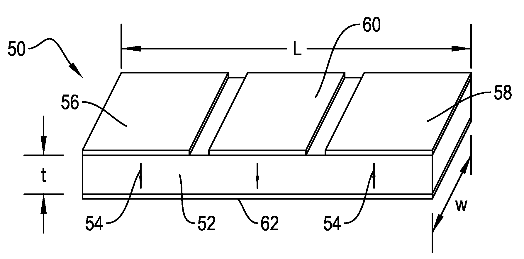
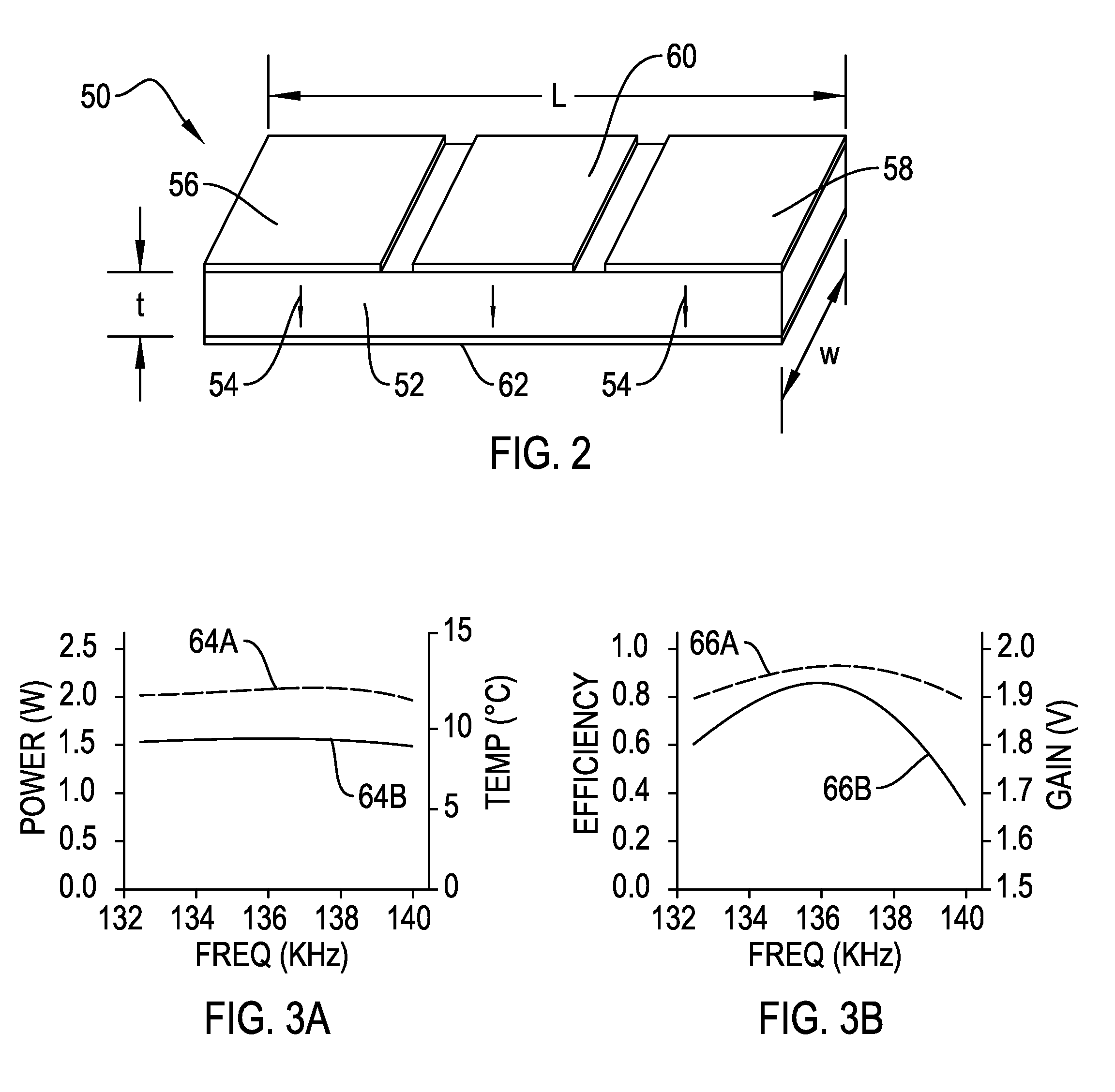
[0042]FIG. 2 is a perspective view of a piezoelectric plate transformer 50 for a first embodiment having a length L, a width w, and a thickness t. Transformer 50 is made from relaxor ferroelectric single crystal piezoelectric material 52 poled in the thickness direction t as shown by arrows 54. The transformer 50 includes two input electrodes 56, 58, an output electrode 60, and a ground electrode 62.

[0043]It should be noted that the configuration with uni-directional poling is preferred in the sense of simplicity and production cost, considering the manufacturing process of relaxor-based piezoelectric single crystals. Initially 17×3×31 mm plates of lead zirconate titanate (PZT) ceramics, undoped and manganese-doped PMN-PT single crystals were manufactured. Properties of these materials are listed in Table I.

[0044]Specifically, hard PZT APC84 I (a product of APC International) was utilized, and the 0.79 Pb(Mg1 / 3Nb2 / 3)03-0.21PbTi03 single crystal samples were fabricated using a solid-...

second embodiment

[0054]A second embodiment and suitable configuration for the application of a single crystal transformer is illustrated in FIGS. 4A and 4B. FIG. 4A is a top view of a uni-poled transformer 70 having a ring-dot electrode pattern. Ring-dot electrode pattern has an inner electrode 72 and an outer electrode 74 formed on one surface of a single crystal piezoelectric element 76. Section line 4B indicates the section line for FIG. 4B. FIG. 4B shows uni-poled transformer 70 in section. Inner electrode 72 and outer electrode 74 are shown in section on top of single crystal piezoelectric element 76. Element 76 is poled in the direction shown by arrows 78. A ground electrode 80 is positioned on an opposite surface of element 76 from the inner electrode 72 and outer electrode 74. Inner electrode 72 has an inner electrode diameter 82, and an outer electrode 74 has an outer electrode diameter 84. A distance 86 separates the top and bottom surfaces of element 76. The areas of inner and outer elect...


PUM


Abstract

A piezoelectric transformer includes a single crystal relaxor ferroelectric element poled along a [0 11] direction and selected from the group consisting of PZN-PT, PMN-PZT, PZN-PT and PMN-PT. The element has two opposed surfaces substantially perpendicular to the [0 11] direction with an input electrode and an output electrode positioned on one surface. The output electrode is isolated from electrical communication with the input electrode. A ground electrode is positioned on the second, opposed surface. Input electrical energy results in piezoelectric change in the element that is mechanically coupled through the element to generate piezoelectric output energy.

Description

STATEMENT OF GOVERNMENT INTEREST[0001]The invention described herein may be manufactured and used by or for the Government of the United States of America for governmental purposes without the payment of any royalties thereon or therefor.CROSS REFERENCE TO OTHER PATENT APPLICATIONS[0002]None.BACKGROUND OF THE INVENTION[0003](1) Field of the Invention[0004]The present invention is directed generally towards piezoelectric transformers, and in particular, to improvements in efficiency and power density for high power single crystal piezoelectric transformers. Naval and commercial applications of the present invention include compact AC / DC or DC / DC adaptor / chargers for personal computers, communication devices, and portable x-ray units. The transformer can be combined to drive ultrasonic motors and motion devices for integration with unmanned autonomous vehicles in lieu of electromagnetic devices, thereby eliminating electromagnetic radiation and interference problems with navigation de...

Claims


Application Information

Patent Timeline
Patent Type & Authority Patents(United States)
IPC IPC(8): H01L41/047
CPCH01L41/107H01L41/18H10N30/40H10N30/85
Inventor UCHINO, KENJIZHUANG, YUANURAL, SEYIT OAMIN, AHMED
Owner PENN STATE RES FOUND
Why Eureka
Try Eureka